 timonsku
Notice: A lot of the stuff explained here is a bit outdated. Have a look at my project logs for updated info about the hardware.
Motivation and reasons for certain decisions:
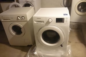
The inital motivation for the project was to build a hardware (as cheap and un-intrusive as possible) and software that was able to tell everyone in the house whether or not any of the washing machines were in use, my sister and her husband that are living one storage above me recently got a child and since then the washing machine usage has heavily increased. At the moment 9 1/2 people live in the house and share 2 washing machines and a dryer. So the machines run pretty much every day for a few hours. Running down with baskets full of laundry just to find them already in use is very annoying, epecially when you come back later and someone else already put in the next machine and you have to wait for another 2 hours to check.
So I thought it would be of great help if everyone could just check on their phone if they can do a laundry run and get notified when the machines finished.
Now you could just have an interface where you push a button whenever you started a new machine but that*s problematic with all those different washing profiles with different run times, as well as the laziness in every person.
Additionally many machines today are very intelligent and don't have fixed run times anymore, which means depending on the load in the machine a run with the same profile could take 50 minutes or 1 1/2 hours.
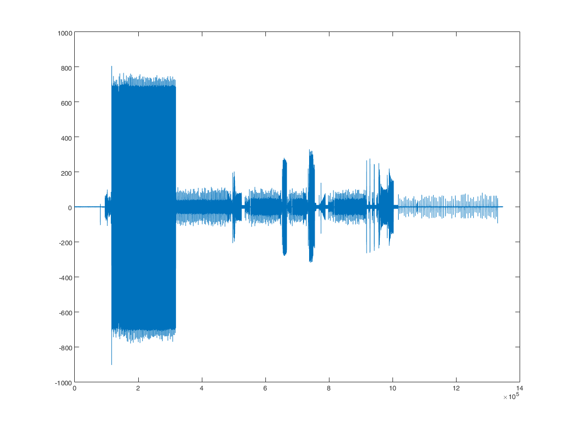
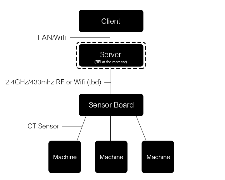 So a more reliable and automated solution had to be found so I opted for measuring the energy consumption with CT sensors. This is non intrusive, meaning nothing gets stuck onto machines to read a status led etc. which could irritate others that don't know about the system (we have a shared flat in the building that often has temp room mates) or fall off very easily with all the vibrations from the machines without permanently sticking the sensor to the machine.
Also its a universal solution that if made into a product could be self learning, it can work on any machine out there.
What hardware/software have I used?
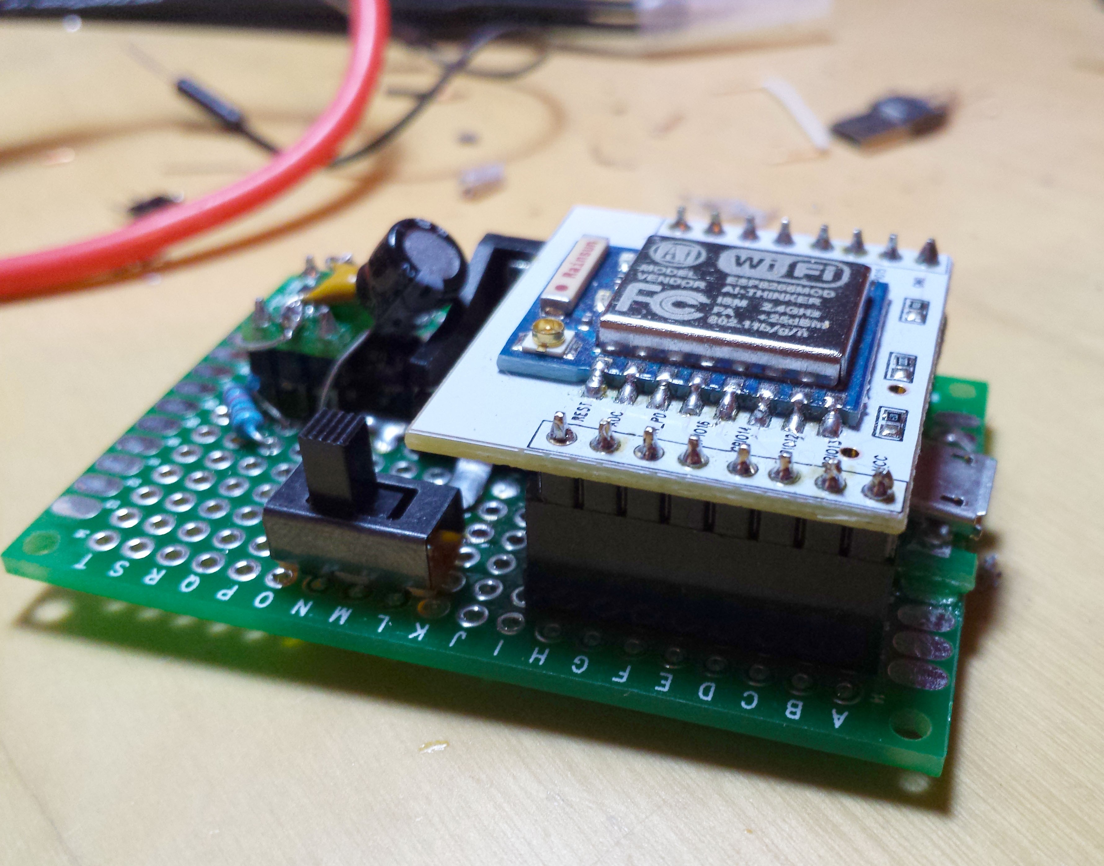
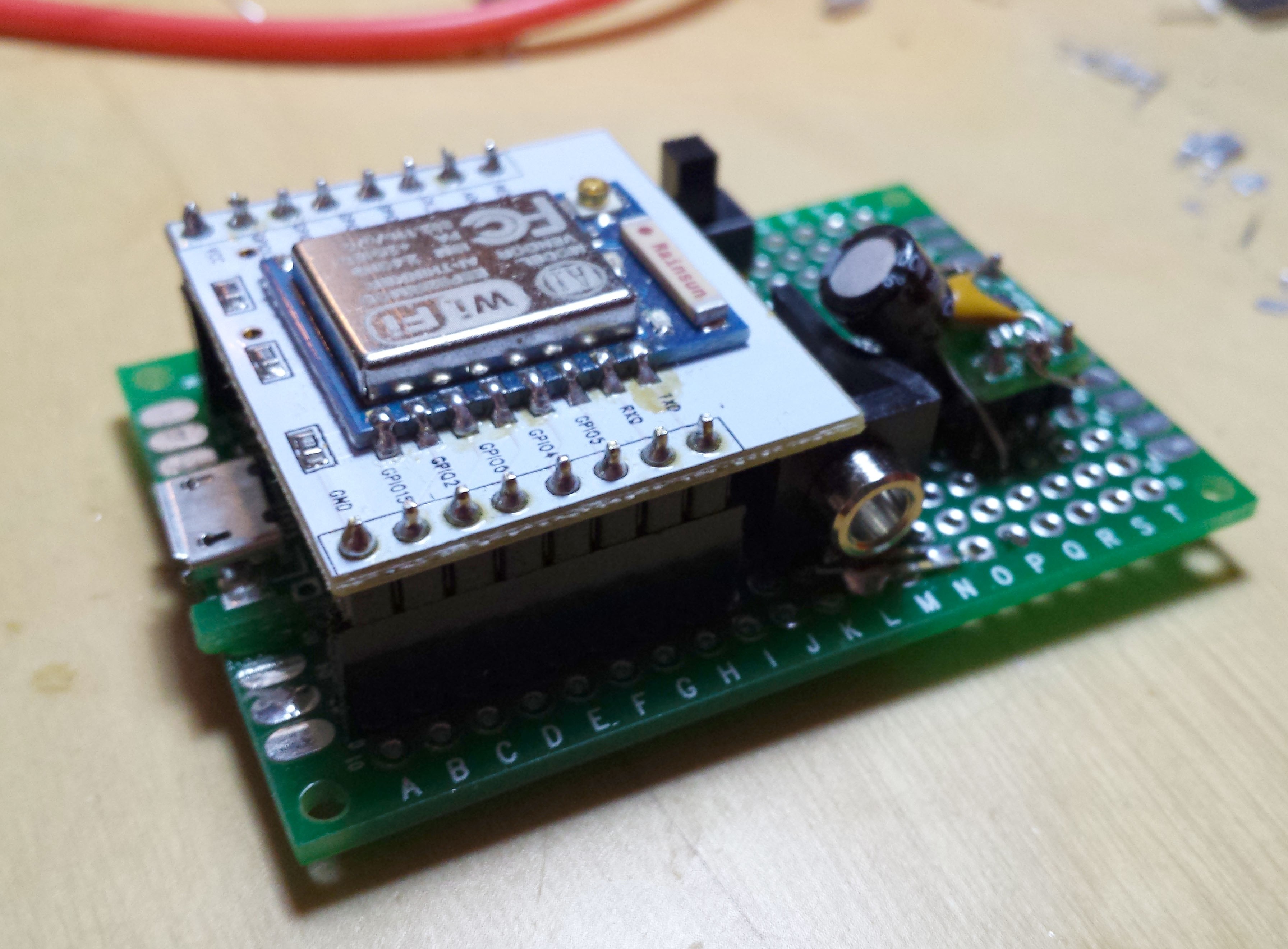
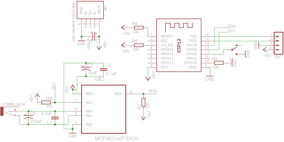
The server and client side are written in JavaScript. The server runs node.js and the client is a simple static website that communicates over WebSocket to the server. The ATtiny85 is programmed in Arduino C/C++ and makes use of the EmonLib from the OpenEnergyMonitor project as well as VirtualWire for the 433MHz communication between ATtiny and Raspberry Pi.
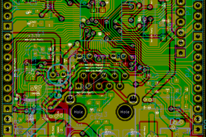
The prototype sensor board costs about 4€ when ordering components in small quantities (1-10pcs). A single CT sensor clamp costs about 5€. I'm using the SCT-013-000. So monitoring a single machine wouldn't cost more than 9-10€. Not including the server. So the 35$ (more like 30€ in the EU) of an RPi comes on top of that or my current plan to use a VoCore which would cost only 20$/14€ and has WiFi. So with a VoCore I would have a total cost of about 25€ and that's for a prototype.
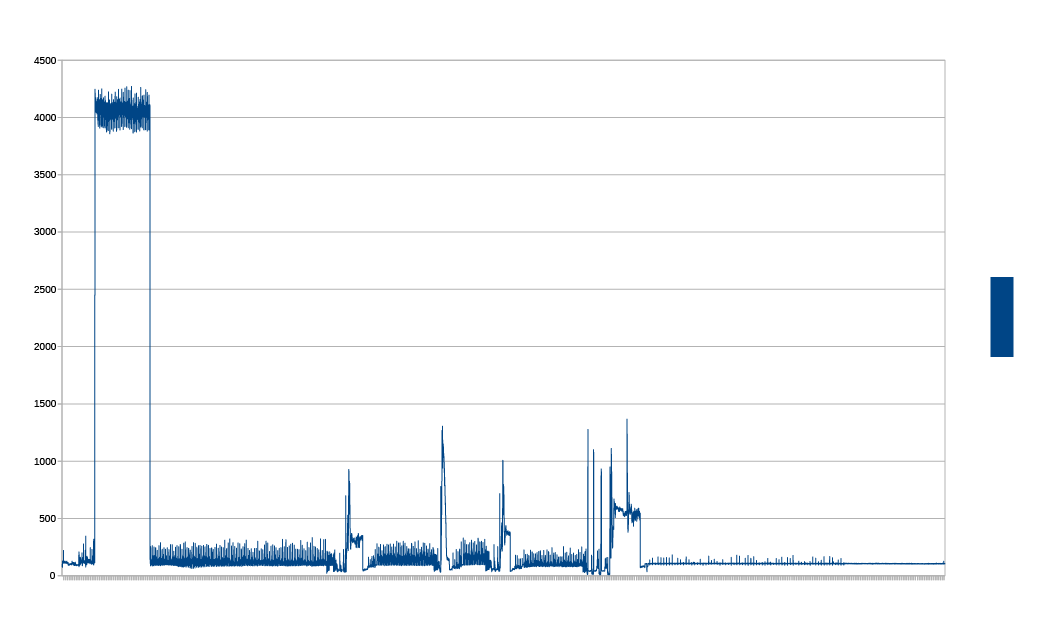
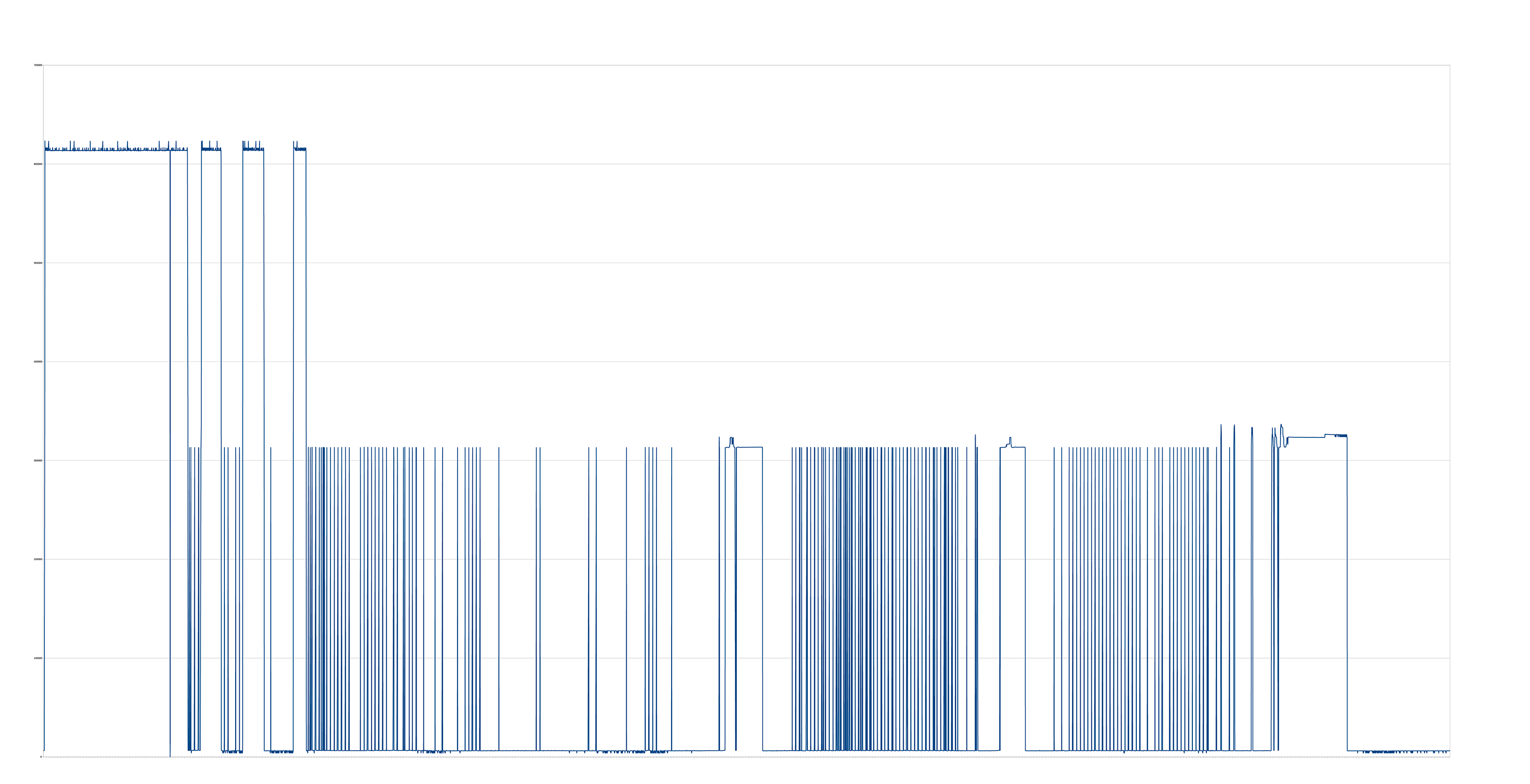
Though as I'm currently having issues with accurate current sensing I will probably opt for some more expensive components.
How does the client software look/work?
 The interface should be as easy to use as possible. The user could be of any experience level regarding technology. While I don't think the 80 year old grandma from downstairs will use this, at least someone who owns a smartphone or computer should have no problem using the system.
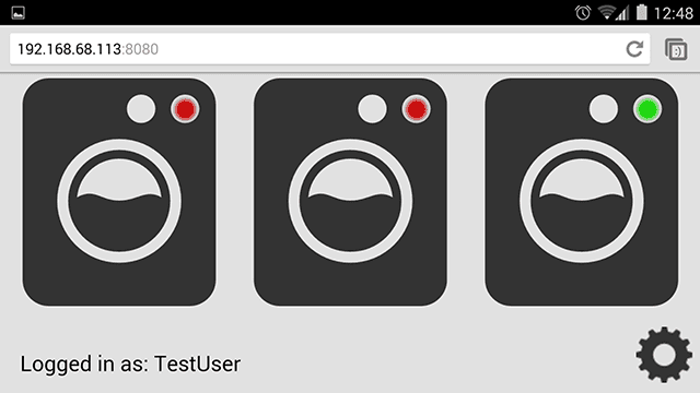
So I opted for a mostly image based design that is easy to grasp in seconds. Green machine means ready to use, red means currently in use. Ideally the system is set up so the machine icons represent their physical arrangement.
I also didn't want to have accounts in the conventional sense. All the user has to enter on a new device is a unique name. That can be a either a nick name or their actual name. Optionally they can also set a password for their account afterwards. If the want to protect private information like an email address used to notify...

 Lars Knudsen
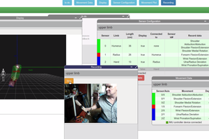
 Jonathan Kelly
 Xasin
Xasin