 Leo
LeoHi all!
For those of you who are setting up projects with inductors, coils, motors, relays and other big inductive things alongside electronics, I have a piece of advice. Most of the time we have to be mindful of them. While setting up 'fresca' to run in a real beer brewing environment, I ran into a lot of trouble with inductive back-spikes. It is a very well known and documented subject for engineers working in industrial environments, but for some people it's not clear as to what happens and when it can become a problem.
Going through school, we used to use a lot of relays, and what your teacher tells you from the first day is: 'you better put an 'anti-parallel diode' across the coil of the relay', and rightly so, you wouldn't want to burn your transistors by the dozens. What is happening? It turns out that inductive elements, like the coil of a relay, store energy in the form of magnetic flux in the coil's core. When you turn-off the current flowing through it, it will try to continue how it was (with the current flowing) until it runs out of energy. Since the circuit is open, it's almost impossible to keep a substantial current running so the physics kicks-in (think Faraday's law) and there's a huge reverse voltage spike applied by the inductor in order to keep the same current flowing. This voltage back-spike could be in the order of kilo-volts (many times it is). So if you have a transistor turning on/off a coil it will face the inductive back-spike each time it turns it off, and that would exceed the maximum permitted collector-emitter voltage (or drain-source for FETs) in turn destroying the transistor.
Now the diode in anti-parallel configuration is there to fix that problem. Since it's in anti-parallel, the diode won't conduct current most of the time (remember, its resistance to reverse voltages is ideally extremely high), but it will conduct current when the transistor turns-off and the relay's coil creates the reverse voltage back-spike (this reverse voltage is forward-biasing from the diodes perspective). This saves our little transistor from having to withstand that massive voltage transient since the diode will conduct all the excess current until the coil runs out of energy. Wonderful and elegant, huh ?

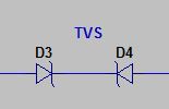
Now if we have AC current, we can't use a single diode to mitigate this effect, since current is flowing in both ways and we don't know exactly the direction of the current when it gets turned off. The solution is in using two Zener diodes in series (and in turn parallel to the coil, with both cathodes facing opposite directions), which will not conduct during normal operation, and will start conducting once the back-spike rises close to the Zener voltage. That means we have to choose the Zener voltage of the diodes to be higher than the peak value of our AC voltage so no conduction happens during normal operation of the circuit.
Now, luckily, there are diodes created only for the purpose of suppressing these voltage back-spikes, they are called Transient Voltage Suppression diodes (TVS diodes). They come in two flavors, unidirectional (DC applications) and bidirectional (AC applications). One important parameter of these diodes is 'Maximum reverse stand-off voltage', this is the maximum voltage at which no current is conducted by the diode hence it has to be selected according to the DC or AC voltage of the application.
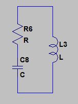
There is another solution, but it requires a bit more thought to work properly. It works by using a resistor and a capacitor in series, which are in turn parallel to the coil. This circuit is called a 'snubber' circuit. The values of R and C have to be calculated and that usually means we need to know/measure the resistance and inductance of the coil. You can find more information about this method on the internet.
So how did this affect me in my project you're wondering. All the relays I used were opto-coupled and protected by diodes so they wouldn't destroy the electronics driving it (specially the Arduino!). So this was fine, but when turning on/off the actuators (electrovalves in this case) the Arduino was suddenly resetting itself! Something was going on with voltage back-spikes, I knew this from the start because if I tested the program without any electrovalves or pumps it worked fine. But if the electrovalves were driven by an opto-coupled relay, hence they should be completely isolated from the electronics, how can they affect something in the Arduino board ? Well it turns out that this is when you have to 'hold' your ground :D If the voltage back-spike from an electrovalve is big enough and it happens suddenly enough it can potentially induce currents in close-enough wires (think ground-loop), or it can even go to the mains and get propagated to whatever's connected to it. So the theory is that this back-spikes are so huge that they provoke a ground-bounce in the electronics that makes the voltage of the Arduino power supply drop enough for it to brown-out. I actually simulated this in LTSpice and could see the voltage drop across the Arduino (represented by a graceful resistor). How do we fix this ? Well by using what I just described, diodes, zener diodes, TVS diodes or snubber circuits. Try to reduce the impact of the spike as much as you can. To me the ideal solution is using TVS diodes, but we solved it initially with snubbers in parallel with each of the electrovalves.
Hope you guys got some good pointers out of this, and if you have any question or have anything to add please
PS: Suppressing the voltage back-spikes has the added benefit of increasing the relay life expectancy since the lower voltage prevents arcing on the contacts.
Discussions
Become a Hackaday.io Member
Create an account to leave a comment. Already have an account? Log In.