 muzi
muziIntroduction
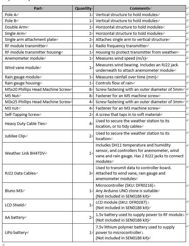
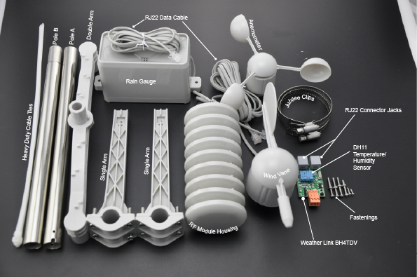
This durable arduino weather station kit includes an anemometer, wind vane, rain bucket and DH11 temperature and humidity sensor. It can transmit data via serial or RF interfaces. This tutorial will demonstrate how to assemble the weather station kit, how to set up basic serial communication to an Bluno M3 and how to output data readings through an LCD shield. From this starting point you can take the kit further and add your own ideas.
Required Components

 Shopping Links
Bluno M3 - A Arduino STM32 ARM with Bluetooth 4.0
LCD12864 Shield for Arduino
Assembly
Insert pole A in to pole B and place double-arm on top of pole assembly. Secure with a self-tapping screw


 Take one single arm and hold up to pole assembly, perpendicular from double arm. Take securing plate and hold to the mating side. Secure together with 4 x M5 machine screws and M5 nuts. Move to desired height before tightening completely.

 If you wish to use the RF communication module, you will need to attach the extra arm. Repeat steps as with the first single arm.
Now it’s time to add the sensor modules. First, take the wind vane. Fit it over one of the fittings of the double arm assembly. Place an M3 nut in the recessed hole of the holder, and thread an M3 machine screw through the hole in the opposite end and secure so that the module is firmly attached.
 We can fit the anemometer module on the opposite end of the double arm. Just like before, fit the module over the moulded fitting, place an M3 nut in the recess on the assembly, and secure firmly with an M3 machine screw.

There are notches in the underside of the double arm for cable management.
Next, the rain gauge. Place the rain gauge over the single arm fitting and secure from the bottom with a self-tapping screw.


If you wish you may also add the RF transmitter module. This is fitted in the same way as the other modules, by fitting it over the arm’s fitting and threading an M3 phillips head machine screw horizontally through the fitting held on the opposite side with an M3 nut.
(Note: there is no RF receiver included in this kit!)

Next we need to connect cables so that data can be transmitted. The anemometer has the shortest cable. Connect this to the jack in the underside of the wind vane module.

 The remaining long cables need to connect to the weather link control board. The cable from the wind vane connects to the “wind” jack on the weather link board (this is screen printed on the PCB next to the jack). The cable from the rain gauge connects to the “rain” jack on the weather link board (again, this is marked on the board).
This concludes the assembly portion of the tutorial. If you like you can tidy up the stray cables with cable ties provided. There are also jubilee clips to secure the weather station to its final place outside, but it is worth waiting until the next few steps are finished before doing this.
The next step is to connect the control board to the microcontroller.
Electronics
Visit the DFwiki page
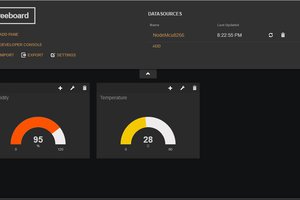
You will find a sample code that measures the following variables:
• Temperature (C)
• Humidity (%)
• Wind Direction
• Average wind speed per minute (m/s)
• Average wind speed over 5 minutes (m/s)
• Rainfall in 1 hour (mm)
• Rainfall in 24 hours (mm)
• Barometric Pressure (hPa)
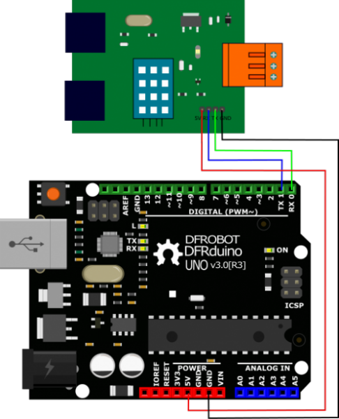
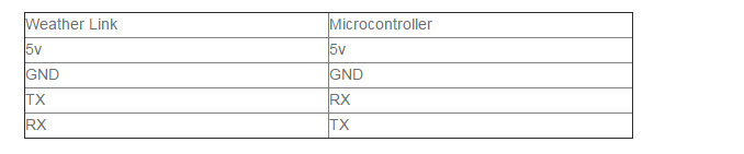
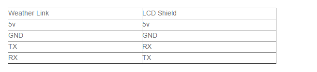
Make the following connections from the Weather Link board to your microcontroller:
 Copy and paste the wiki sample code in to the Arduino IDE and then upload it to your microcontroller. You can view the output on the IDE’s serial monitor. Readouts should be printed every half second.
This is fine, but it is inconvenient and unlikely your weather station will be tethered to your computer in use, so let’s add an LCD shield to our setup. Remove all wiring to the microcontroller and then stack the LCD shield on top of it, and then reconnect the wires to the shield as before.
Not only does this shield provide an LCD interface to output data, but it also adds extra I/O pins if you want to add more sensors or actuators.
Now that...
 Capt. Flatus O'Flaherty ☠
 Mr. Sarful hassan
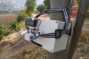
 Guillermo Perez Guillen
I encourage you to read website www.simplyclime.pl. Enables connection of the weather station with the mobile application.