 Mark Mullin
In addition to all of the EE work in bringing up the other two Beaglebones and 16 new cameras, I’ve started designing the robotic platform that will carry the camera. Right now, the single equatorial ring lives on the static platform shown here.
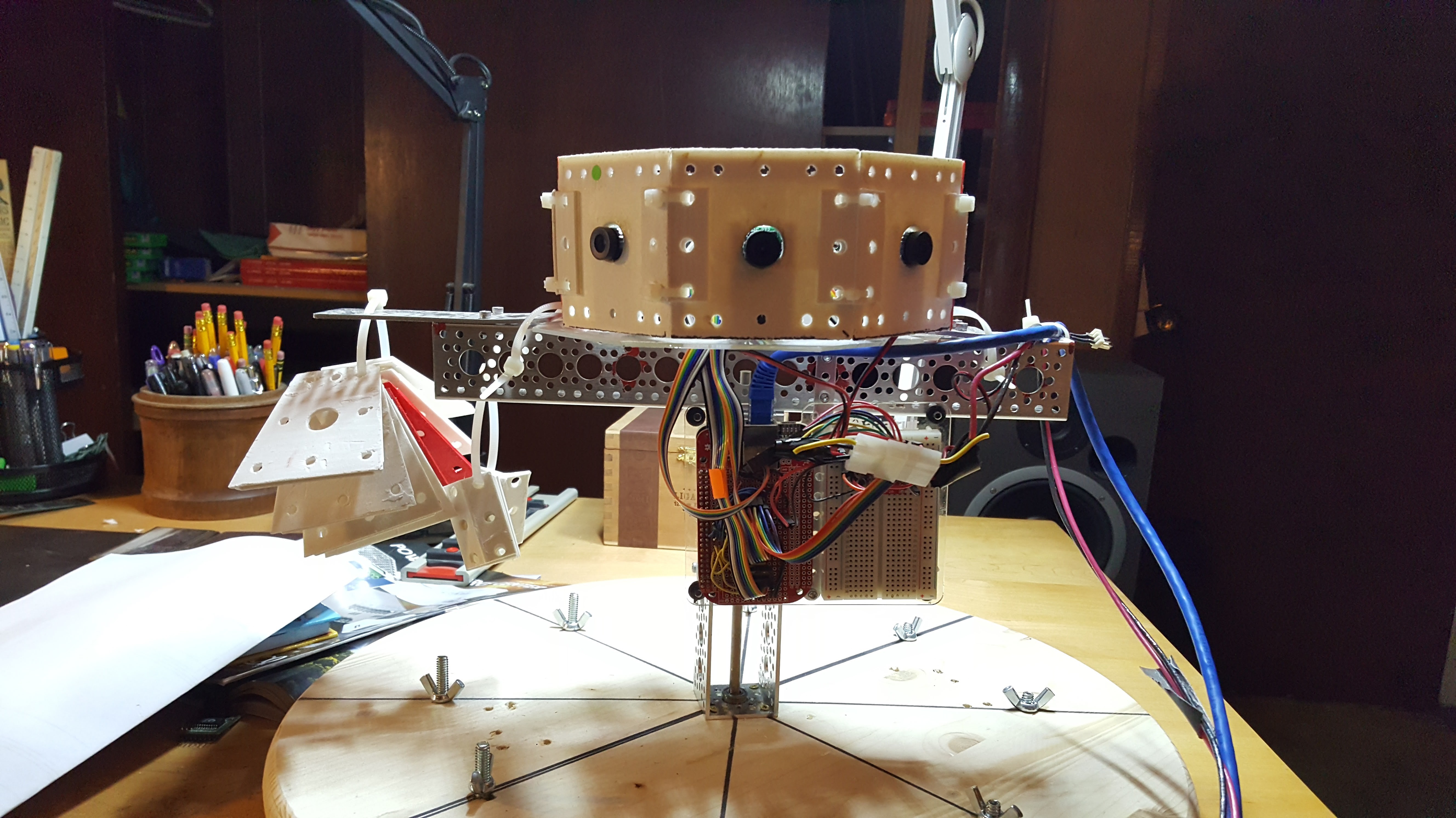
The circuit assembly is a Beaglebone, a custom cape breaking out SPI and I2C for the cameras, and a 74VHC139 in a dip mount in the breadboard
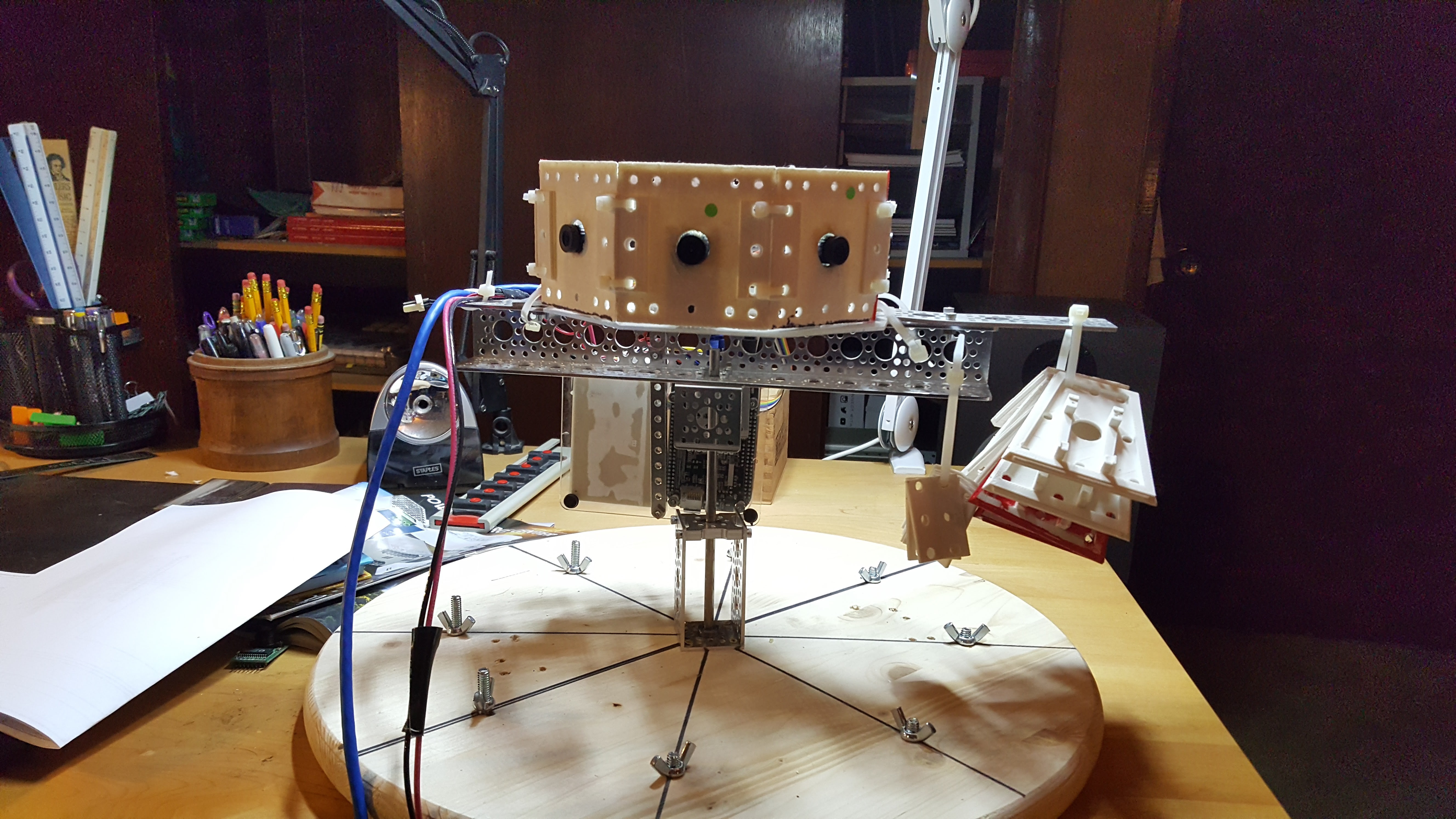
Another view - the stuff zip tied to the right are the angled plates for the upper 45° ring. The lower ring will be the same.
This equatorial ring, along with the upper and lower 45° rings will migrate onto a platform where the computer can move it up and down over a 20” range and can step over a -45° to 45° rotation around the up vector at high speed. The up and down translation adds useful depth information, but the high precision high speed rotation around the vertical axis allows the system to develop a 3D depth map of its environment from a static position, and use the vertical translation to continue to refine the accuracy of the measurement.This is a key part of my hypothesis - can you fuse simply calculated structurally predefined 3D as insects might perceive it with microsaccade scanning to compensate for the weaknesses in our tooling ?
I use Actobotix components for the mechanical assemblies
that I don’t print, sourced from www.servocity.com. I must admit one of the reasons for this post
is that I’m prepping a document for ServoCity on the Quamera project, since it
seems that projects that impress them net a parts discount, and I have a
ravenous parts budget. The technical need is to have 20” or so of translation
over the vertical axis, to have about 45° of bidirectional rotation around the
vertical axis at high speed. This gives
the cameras a full RGBD sample set and additional parallax data sets from
vertical translation.
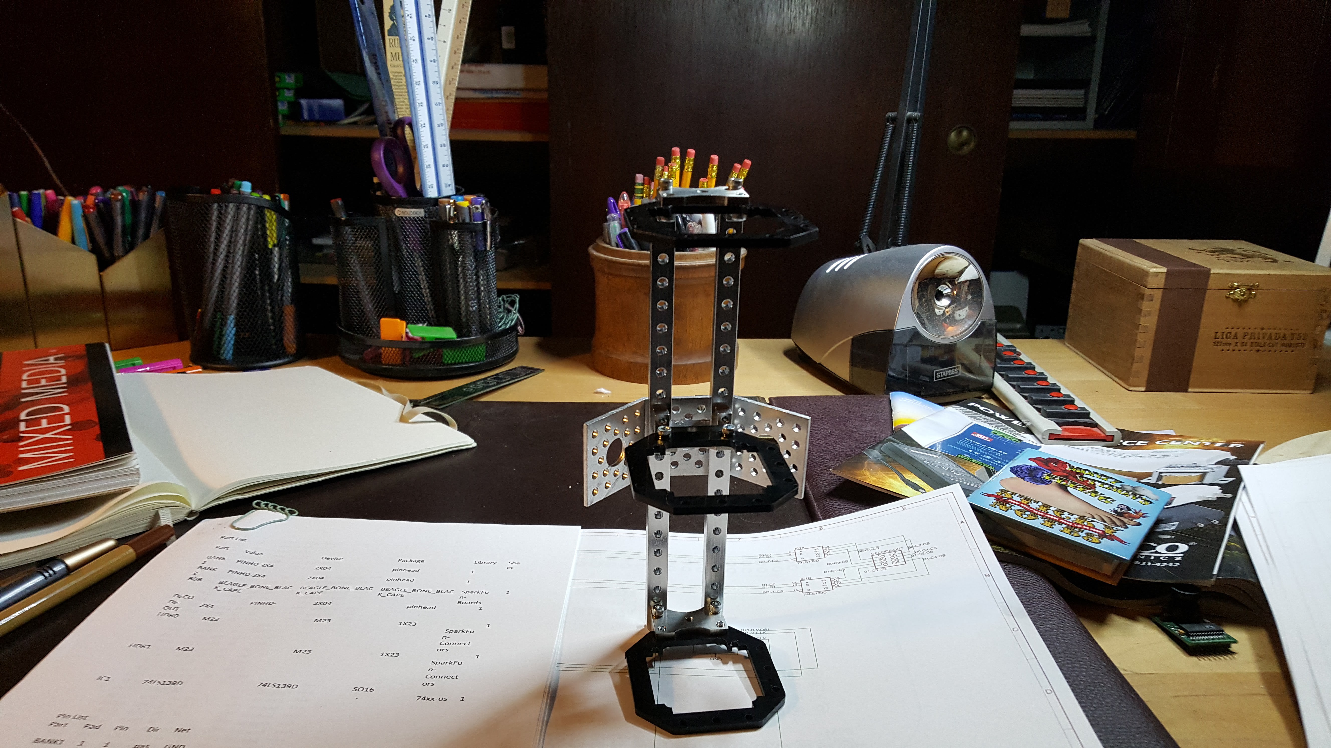
The basic idea is that an armature slides up and down a vertical rail, and all of the camera hardware is attached to this armature – Here are some views of the partially assembled armature, where only one side has the structural rails and one of the 4 mounting surfaces.
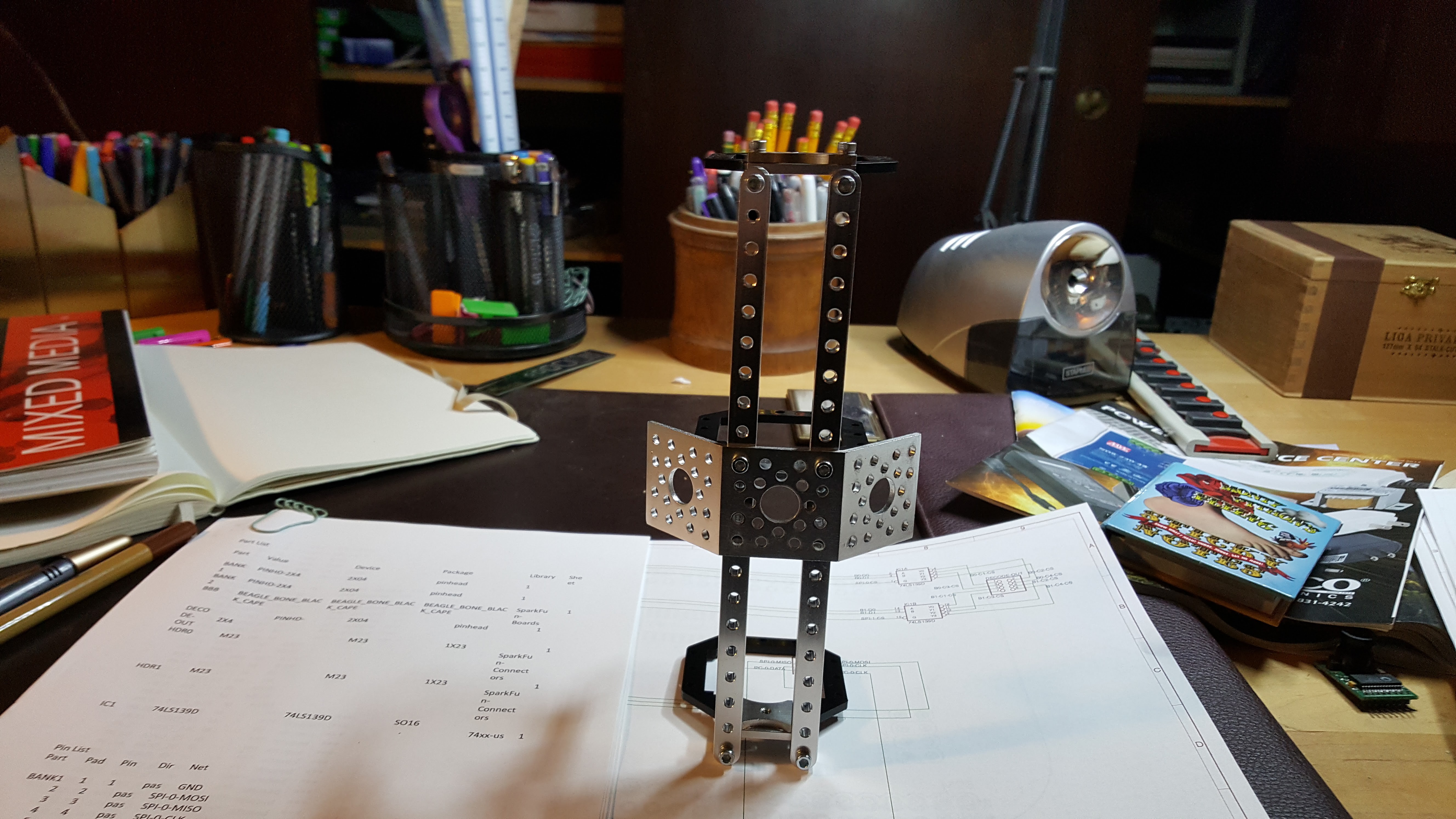 Top down view - a fully assembled armature would have 4 of those dual 45° brackets vertically.
 side view - the rails in the previous view would be present here as well, however this would not carry any angle brackets.
 back view - this would also have the two vertical structural elements like all others and would also carry 4 vertically mounted dual 45° brackets
Completed, this will be a rather healthy collection of
aluminum, riding on 3 Delrin brackets sliding up and down the camera mast. The goal is to have an armature that wiggles
as little as possible, as wiggling/backlash/etc can be viewed as a ranged
random function and all those do is make my learning algorithms miserable. Doesn’t matter how many dimensions I chase
that noise into, if I can't linearly separate it, its sand in my gears. This is a class of problem that seriously frightens me, because it just shows up and says 'Bummer, you rolled a 2 - your maximum certainty is +- 20%.
When it’s completely constructed, the rails you see on one side of the armature will be duplicated on all four sides, and the mounting plates will be running from the top to bottom of the armature at 0° and 180°. All of the 3D printed mounts for cabling and hardware will attach to these plates and a series of struts will connect the external camera plate framework. Part of this is I don't like wiggle. The other part is that I only have one vector to transmit force from my lead screw to the armature, so I need to believe in structural integrity.
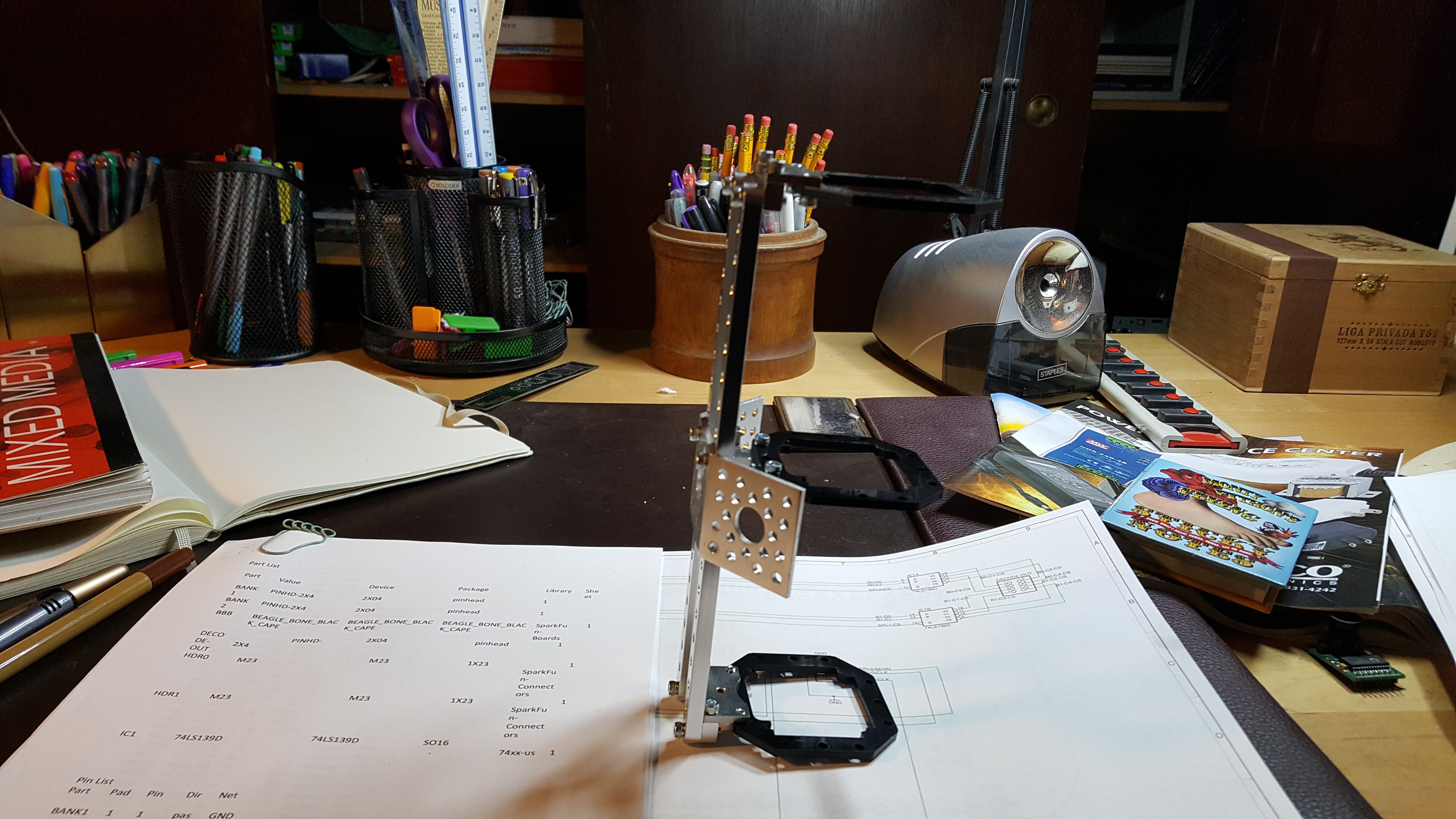
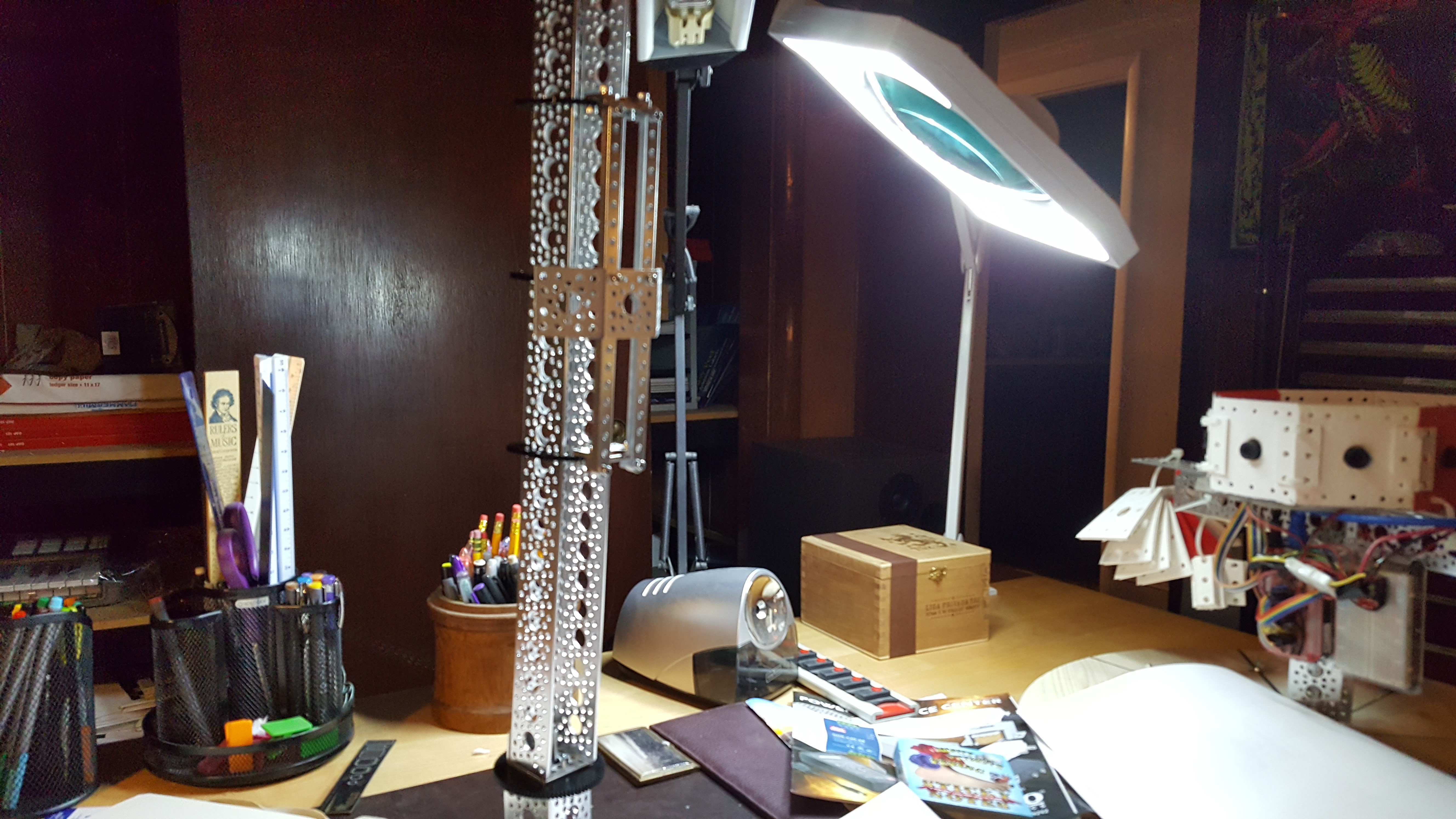
Here are views of the mast with the geared rotation assembly at the bottom and the armature positioned in the middle. The rotation assembly is used to rotate the mast. To rotate the mast at high speed. With an off balance camera armature moving up and down it. This should be interesting. 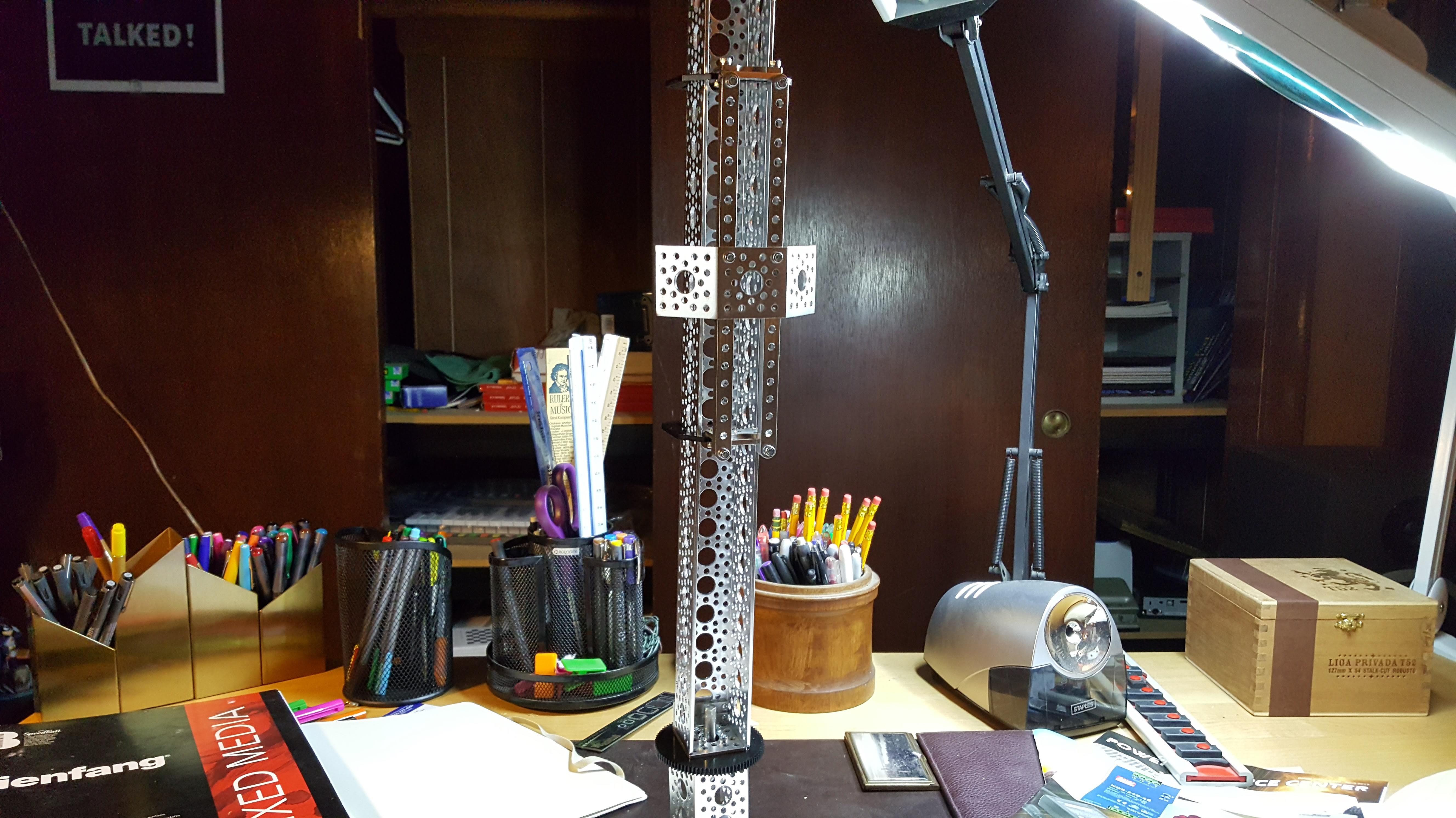
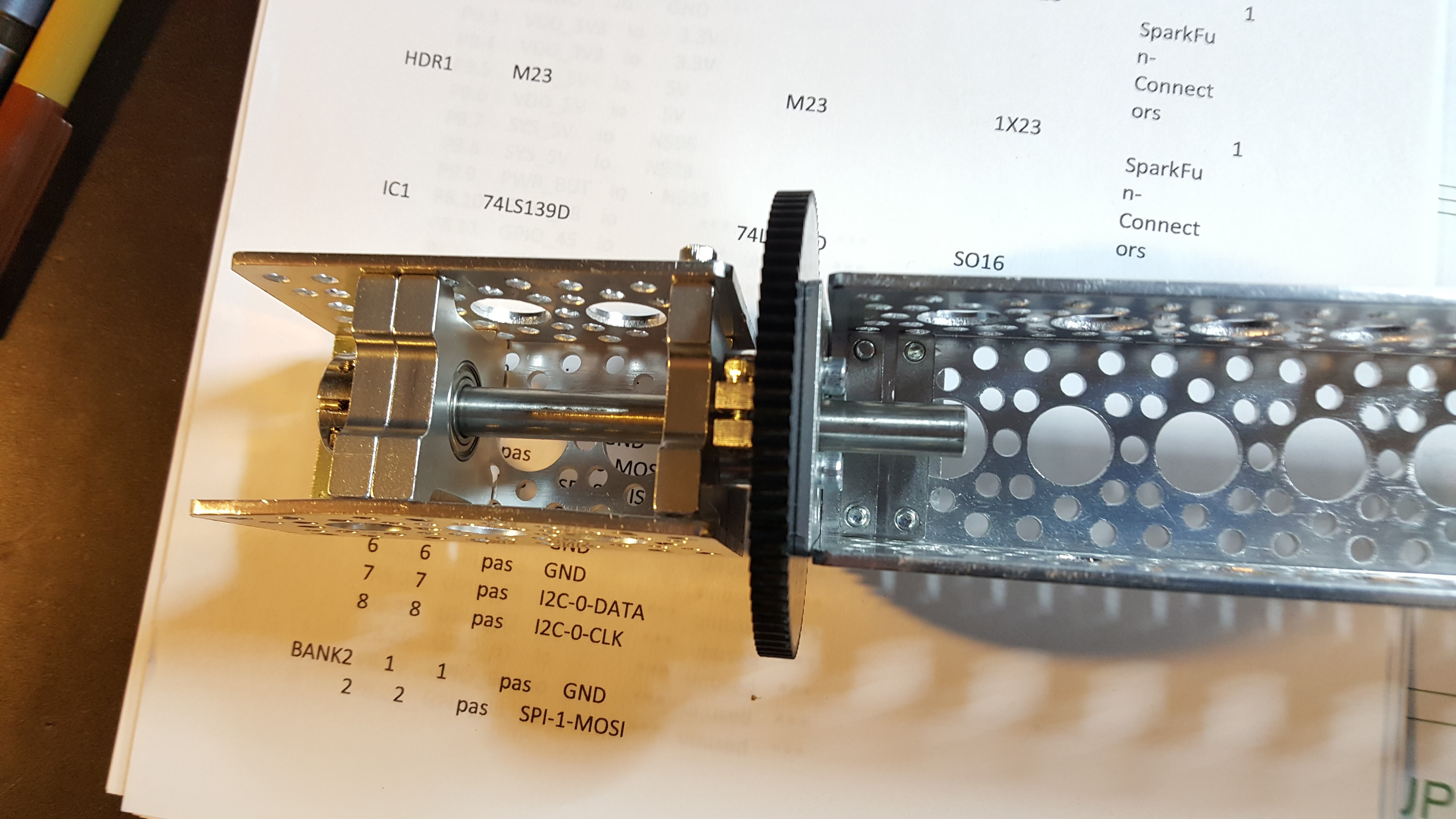
 Here's a closer look at the current rotation assembly prototype. Note I'm switching to a design with two equally spaced pillow blocks on either side of the drive gear. I fear the current design just wants to be a lever.
You may ask why this matters. In the short term, because the math is now calling for more data, i.e. the fusion issues on the fixed image sample are best addressed by first providing static upper and lower feature alignment coordinates. Once that’s done, the next best data is gained from rotating the cameras such that the entire visual field has been covered by overlapping visual fields. When motion comes into play, this rotation will have to be quite snappy. Finally, the vertical translation adds additional parallax data, albeit at a grosser resolution, but good enough for a network or several. At this point the system is capable of resolving a static 3D environment in 3D accurately at high resolution.
Discussions
Become a Hackaday.io Member
Create an account to leave a comment. Already have an account? Log In.