willbaden
-
Code Release
11/23/2014 at 15:45 • 0 commentsMatrix_Display code can be viewed here:
https://github.com/baden0001/Matrix_Display
If you have questions, leave a comment or shoot a message over.
-
Omaha Mini Maker Faire
09/15/2014 at 00:13 • 1 commentThe display survived the whole day of the maker faire. A picture of it can be seen on the Claw Machines project logs page. It continuously scrolled "OMAHA MINI MAKER FAIRE 2014".
As for the other stickers that Kritina Panos gave me, here is where the other .IO sticker is now attached.
![]()
-
Speed Control
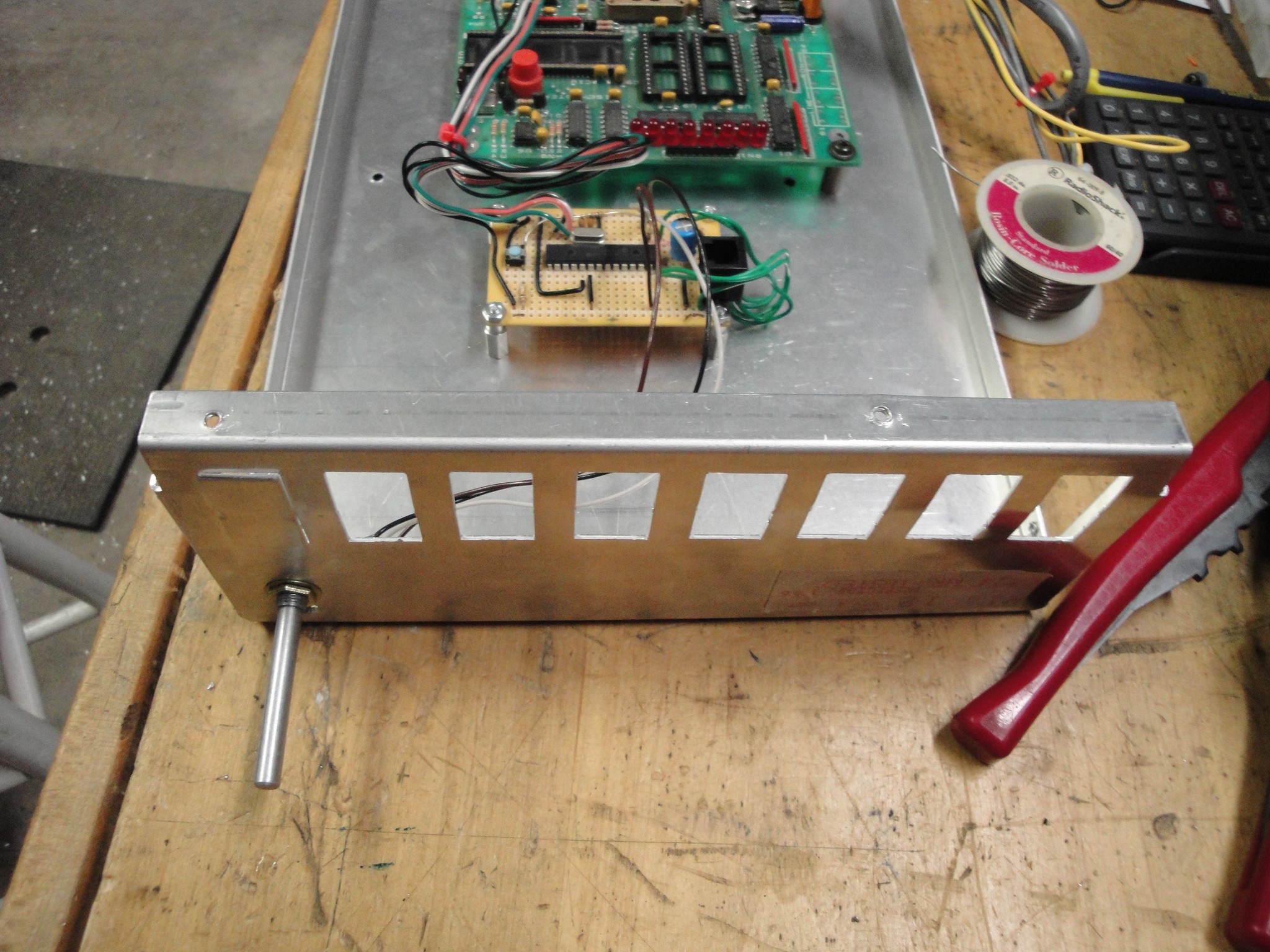
09/03/2014 at 02:24 • 0 commentsFor an input, I used a 10Mohm pot to control the speed of the scrolling. This fed into AN0 of the 16F870 through a 10kohm resistor. The pot is installed on the lower side of the panel for easy access.
![]()
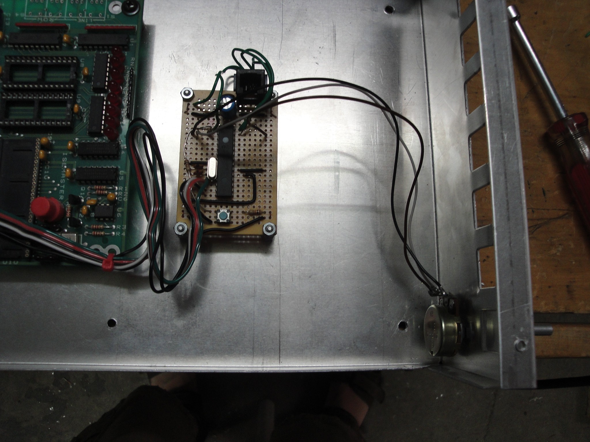
A jack was added to aide reprogramming of the PIC. The is located @ the top of the perf board in the picture below:
![]()
-
New Enclosure
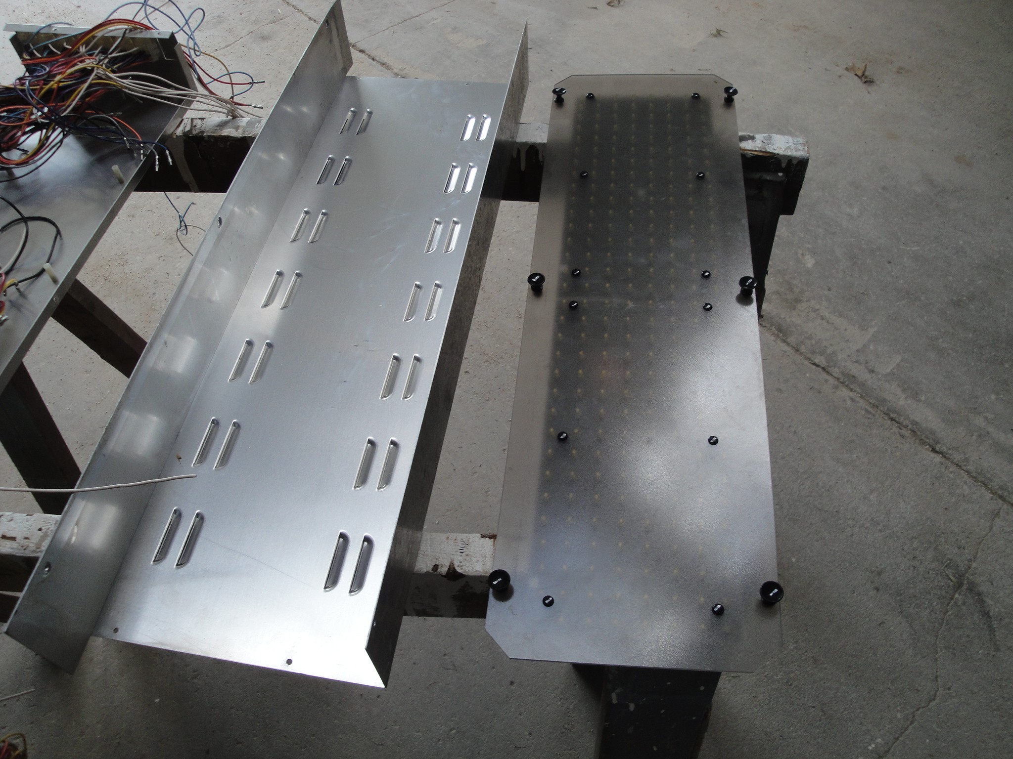
09/02/2014 at 00:17 • 0 commentsThe matrix display is being prepared for the Omaha mini maker faire. It needed to be enclosed to keep prying hands away from the 120V power. The enclosure was a scoreboard controller box that was saved from scrapping. This was the perfect size to fit the matrix display in.
As seen in the picture below, the left hand side is the cover to the right hand side base.
![]()
The cover had louvers punched into it that will eventually be removed for the matrix display to reside.
![]()
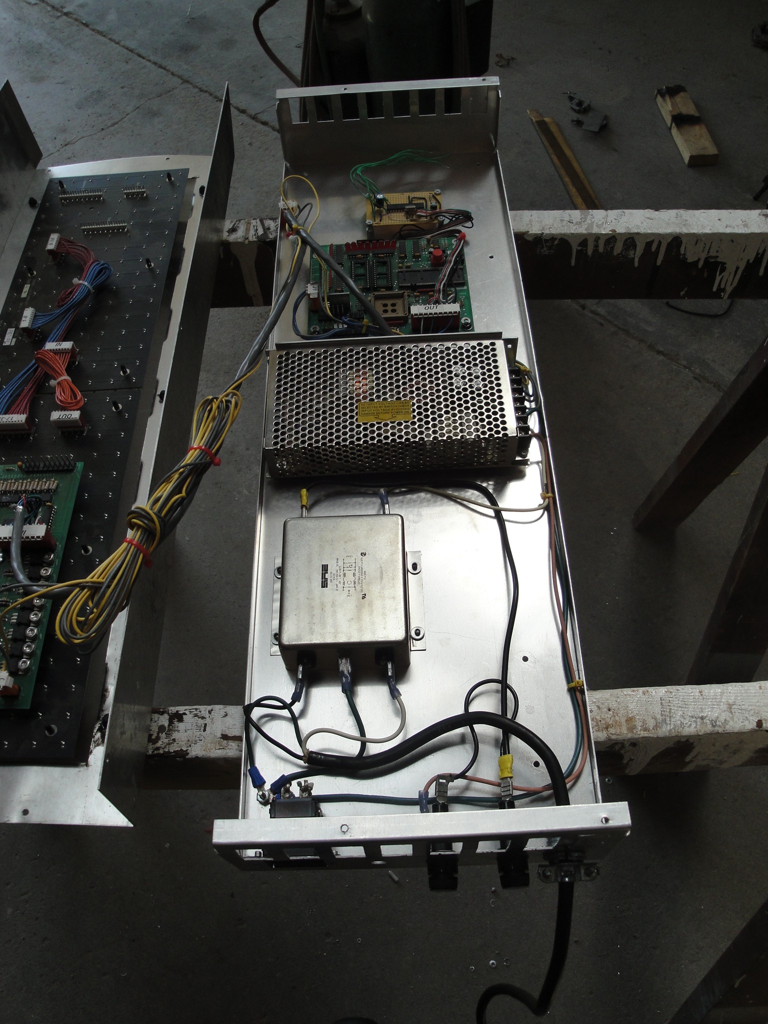
The controller box utilized a noise suppressor which will be reused for the scoreboard controller. The transformer and power plug-in will not be used. Instead a 7.5v power supply and standard plug in cable will be installed.
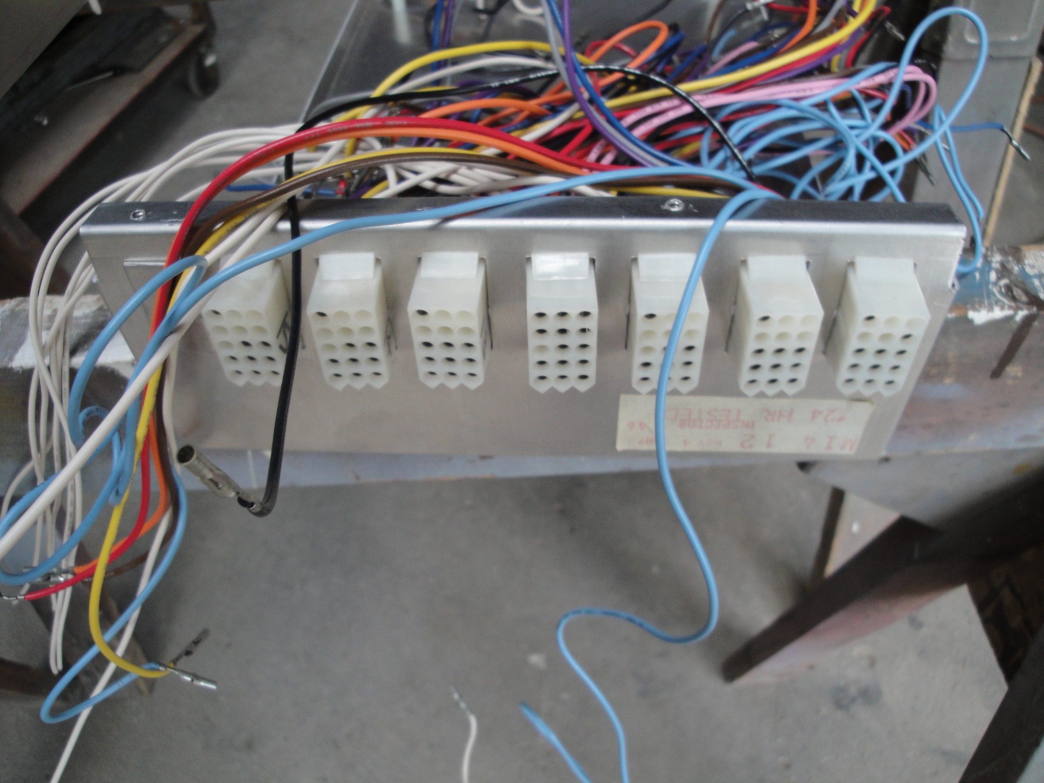
The ends had 7 - 15 pin connectors which were removed. These will be kept for future projects.
![]()
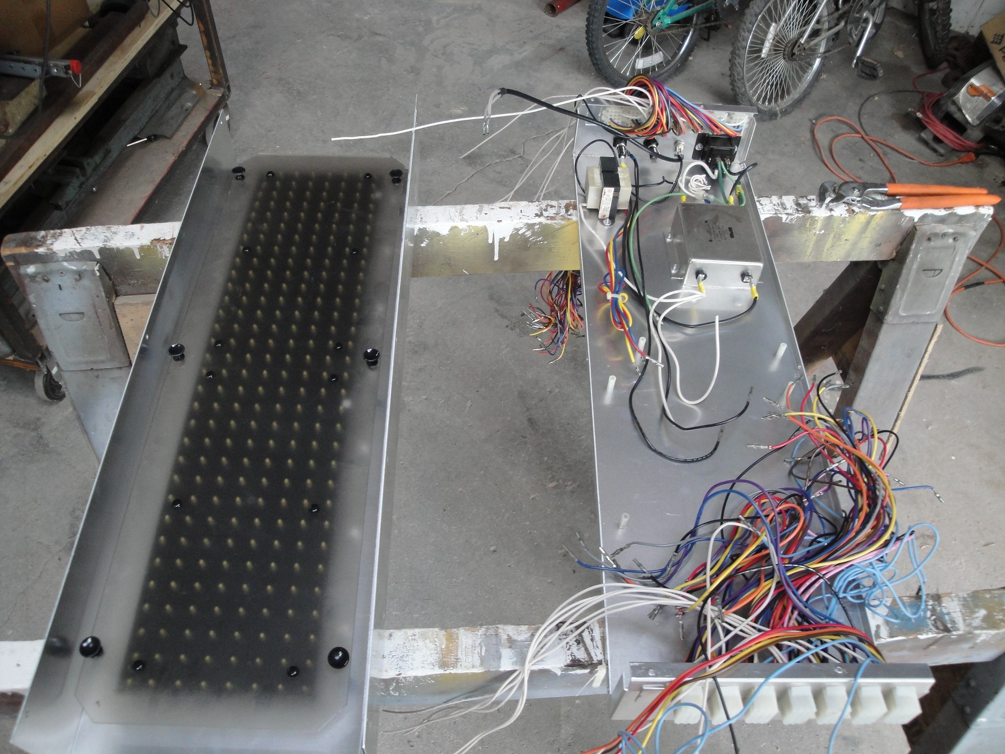
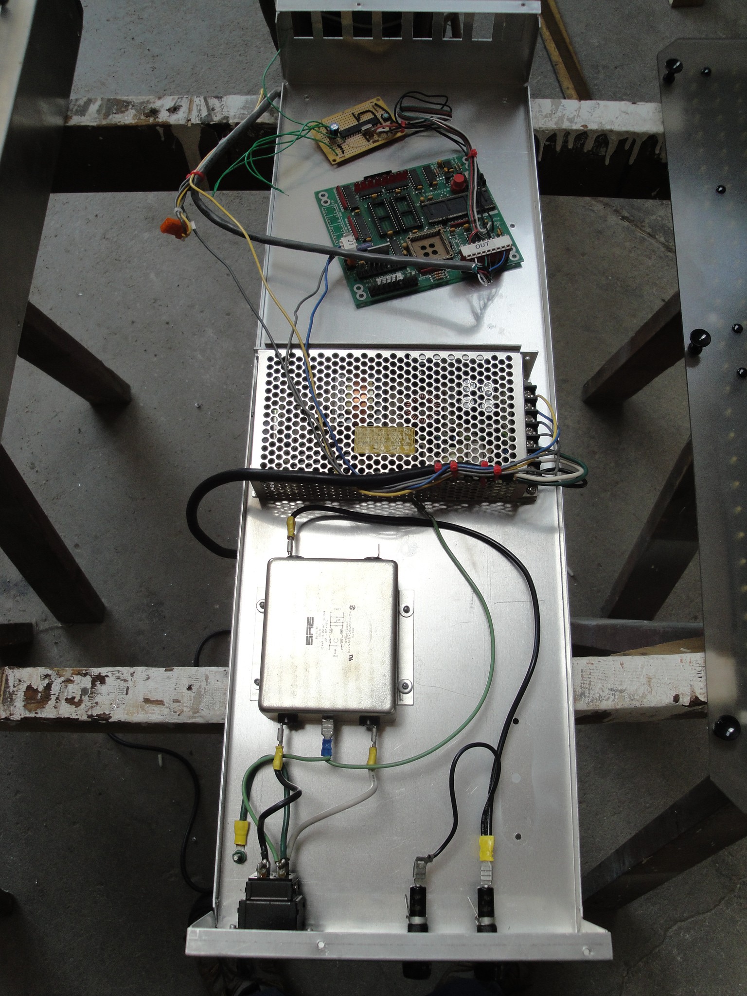
Below is the layout of the boards and power supply. Starting at the top of the picture is the controller board. This currently is configurable only through reprogramming the code to allow for different messages to be seen. I plan on updating this as soon as I can find some more time. The second board from the top is the original controller board. Really the only thing that is used on the board is the 5v power supply and header for connecting to the matrix display. The next component down is the 7.5 V power supply which feeds all the led's and the original controller board. At the bottom is the noise suppressor.
![]()
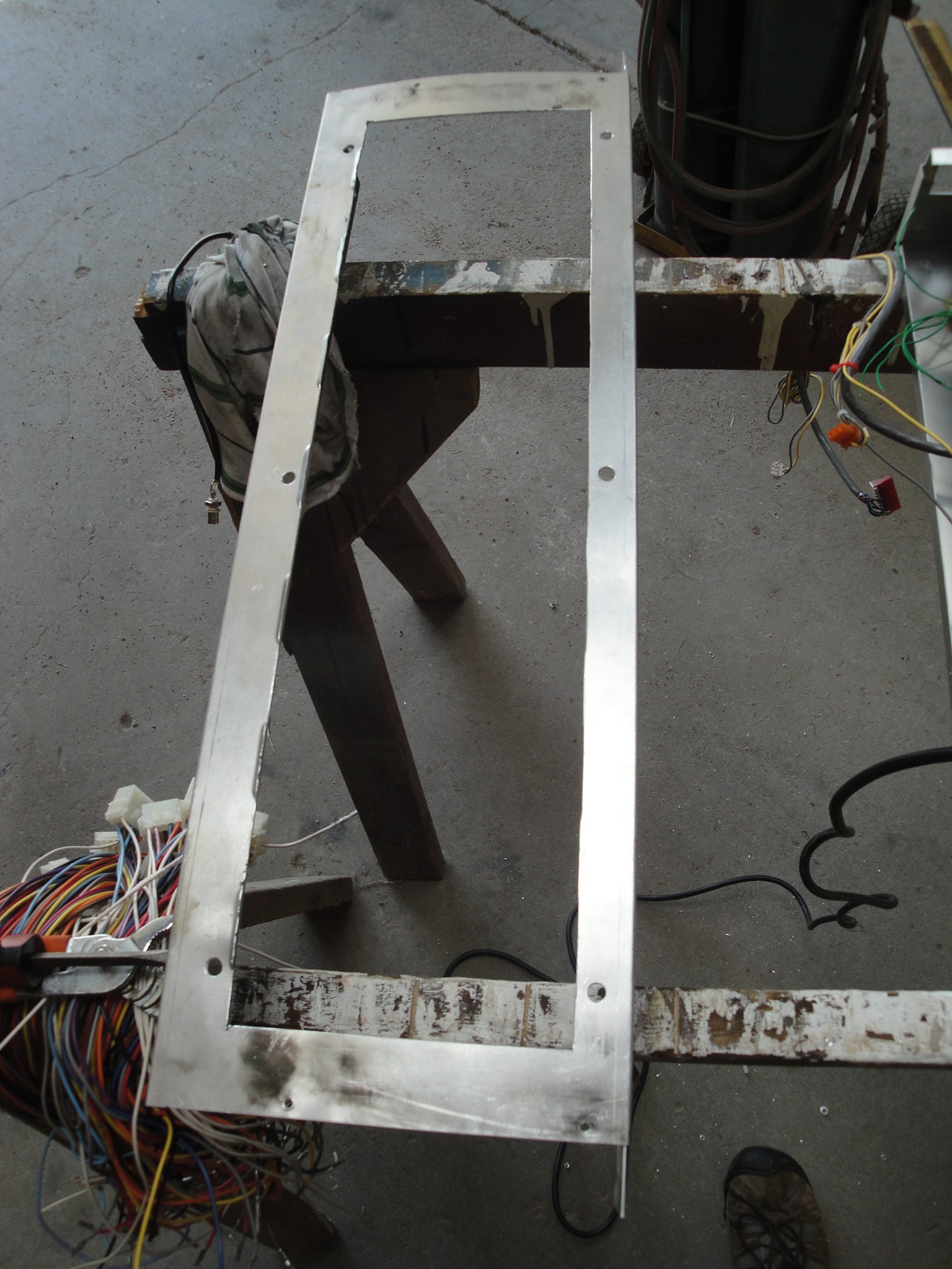
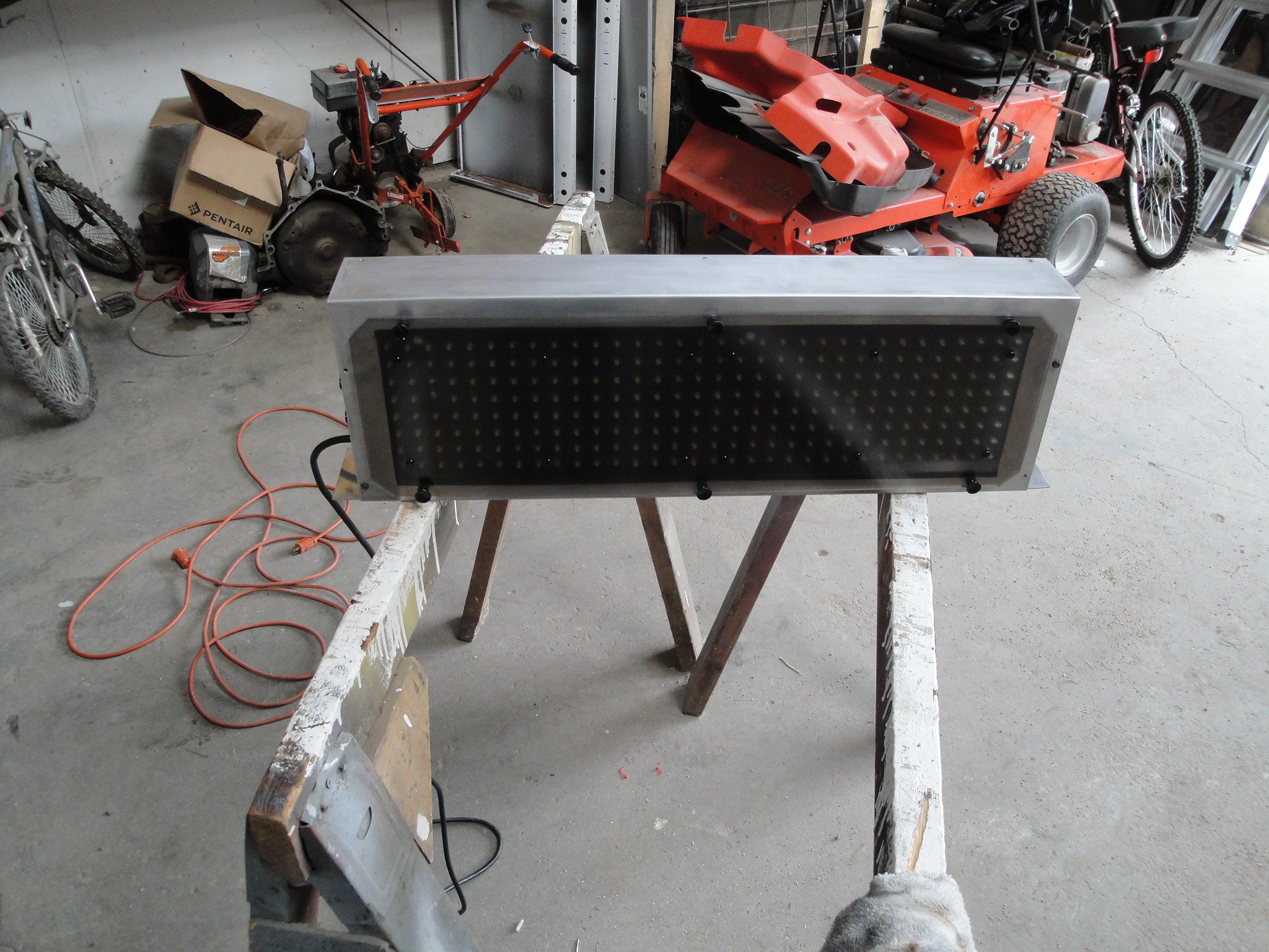
After I knew the components would fit, I then modified the face to allow for the matrix to be mounted. The plasma cutter ended up warping the ends of the face, but once installed on the base, it flattened out. Along the left of the face, the original louvers can be seen. These were hammered down and then some electrical tape was laid along the edge to hide the damage. This made it more eye appealing.
![]()
The boards were then mounted to the base and wired in.
![]()
The matrix was installed to the face and here is the assembled product:
![]()
LED Matrix Fairplay hack
Creating a new display controller for a Fairplay scoreboard LED matrix