 Simon Merrett
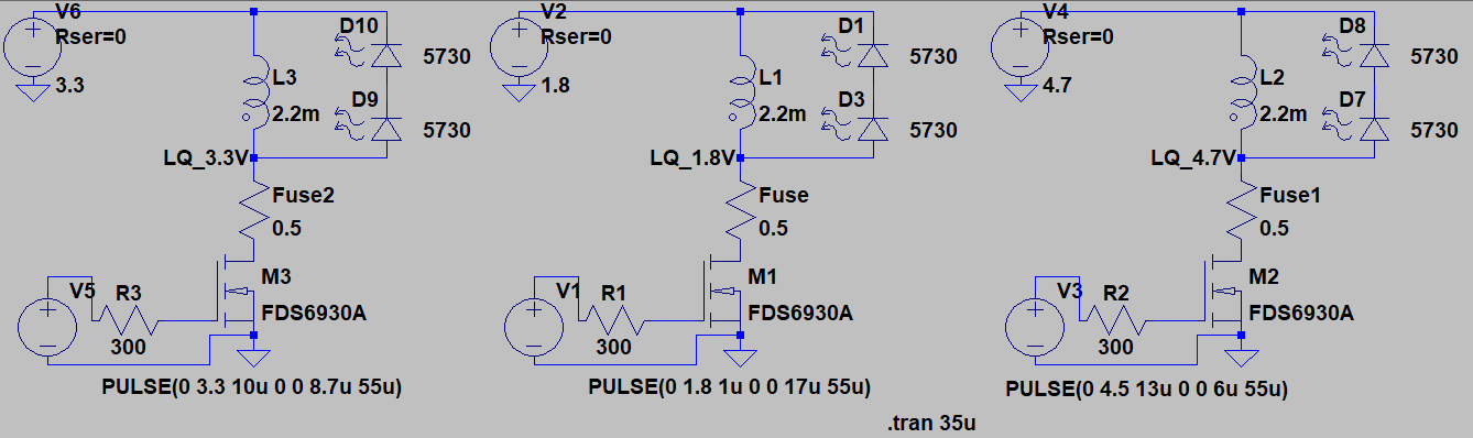
So last log we looked at the pulse durations required to generate 14mA peak sawtooth current with the two "working" extremes of supply voltage - 1.8V at the lower end and 4.7V at the top end. I say "working" because eventually we may look at working with voltages outside this range, particularly at the lower end. However, for now, they will do as a good envelope to design within. For a quick test of whether 14mA peak current (which we calculated would be the most efficient conversion of electrical to optical energy using the inductor boost driver) looks bright enough, I wanted to run it on the V1.1 prototyping board at 3.3V (because that's easy to generate and have matched voltage between Vsupply and Vpulse). Here are the three circuits we're now looking at, which differ in their voltages and pulse timings.
 As before, when I compared the 1.8V and 4.7V supplies, I have adjusted the pulse start times and durations so that all the voltages have their discharge current curve superimposed:
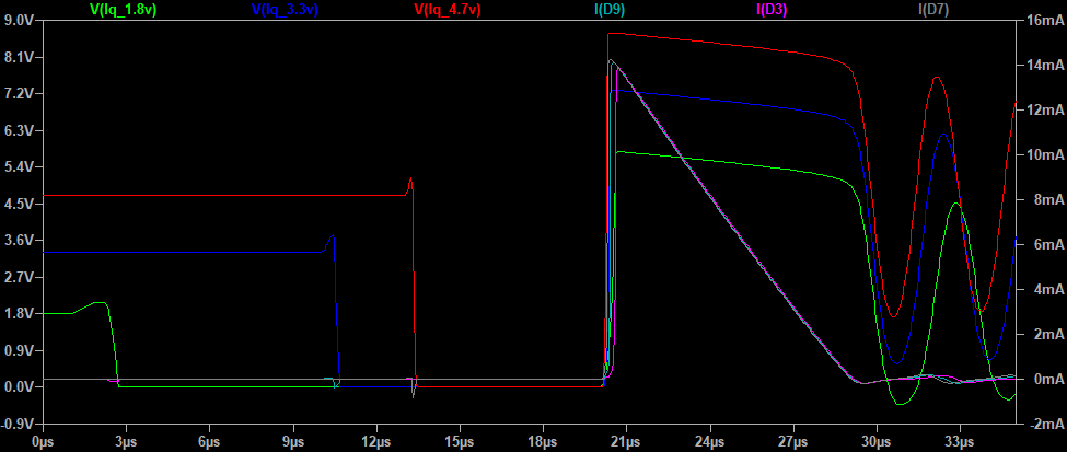
This gives us a theoretical pulse time of ~9us will give us our 14mA peak sawtooth discharge current and a 10us delay before pulsing again will start the new pulse as the inductor voltage swing is on the down slope after the LEDs switch off. To generate this with the ESP8266 and accounting for the added delay of digitalWrite() and loop(), I used these timings to achieve this:
void loop() {
  digitalWrite(D4, HIGH);   // pulse ON
  delayMicroseconds(7);   // generate a 9us delay
  digitalWrite(D4, LOW);    // pulse OFF
  delayMicroseconds(3);   // generate a 10us delay
}
Which can be verified by connecting the oscilloscope to the pulse pin on the ESP8266 with nothing else connected:
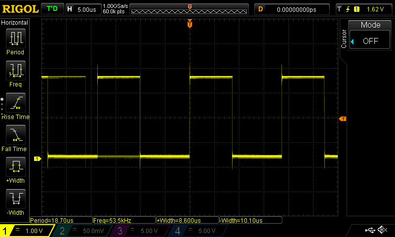
Note that the oscilloscope does the measurement hard-work for you when you press the +Width and -Width buttons on the left side of the screen, displaying times helpfully along the bottom of the screen.
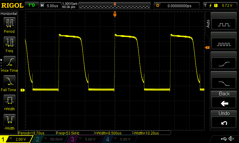
Then connecting the ESP8266 3.3V, GND and pulse pin to the V1.1 prototyping board, we get the following trace:
And now for the all-important brightness comparison. It's hard to convey the difference using a mobile phone camera and words but I'll give it a go:
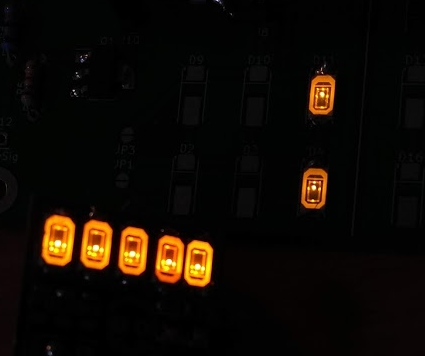
Yapolamp Beta (Left) with all LEDs and Yapolamp V1.1 protoboard (right) with 2S 1P configuration.
You can see what I perceive in this photo, that the Beta is slightly brighter than the V1.1 protoboard. However, I thought it would be fairer to compare 2 LEDs to 2 LEDs, so masked three of the Beta with electrical PVC tape:
 Although the focus is frustrating, their brightness is closer than I initially thought. I went back to the efficiency calcs to see what driving at 20mA peak sawtooth current would do to the efficiency - it would be about 0.91 at 317 Lux/mA relative to the peak efficiency of 348 Lux/mA. Worth considering. Lets see if we can tel the difference in a comparison. According to Spice, we'd need a 12-13us pulse and we would catch the downward voltage slope of the inductor about 14us later. Now to generate that profile on the ESP8266, we need:
void loop() {
  digitalWrite(D4, HIGH);   // pulse ON
  delayMicroseconds(11);   // generate a 12.5us delay
  digitalWrite(D4, LOW);    // pulse OFF
  delayMicroseconds(7);   // generate a 14us delay
}
This timing needed tweaking so that the next pulse catches the downslope from the inductor in reality. This is the beauty of having an oscilloscope to verify what the simulation says. We now need a 13us wait before sending the next pulse. To compare the 14mA and 20mA versions, we will cycle between them, one cycle per second, so each mode will be on for 500ms. Because of the delay introduced by checking the time for pulse length cycling, this is what the code results in for now. You wouldn't go to production with it, but it suits our prototyping needs:
byte pulseOn = 6;
byte pulseOff = 0;
unsigned long present = 0;
void setup() {
  pinMode(D4, OUTPUT); // initialize digital pin as an output.
}

void loop() {
  present = millis();
  digitalWrite(D4, HIGH);     // pulse ON
  if (present % 500 == 0) {   // action this subroutine every half second
    if (present % 1000 == 0) {
      pulseOn = 6;            // ON delay if at a full second
      pulseOff = 0;           // OFF delay if at a full second
    }
    else {
      pulseOn = 10;           // ON delay if at a half second
      pulseOff = 3;           // OFF delay if at a half second
    }
  }
  delayMicroseconds(pulseOn); // delay for the inductor to charge
  digitalWrite(D4, LOW);      // pulse OFF
  delayMicroseconds(pulseOff);// delay for the inductor to discharge
}
We got our nice pulse traces, as desired:
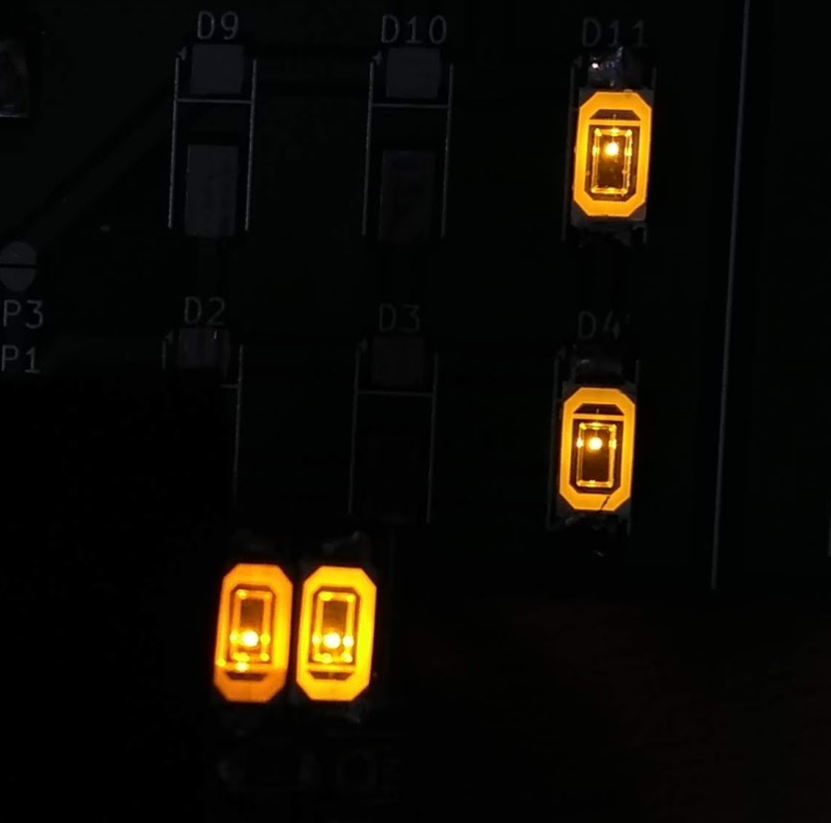
And there is a minor increase in brightness (which is expected, as perception of brightness is not proportional to illuminance). The Beta is the two close-together LEDs in the bottom left and the top right pair are V1.1 protoboard cycling between 14mA and 20mA peak sawtooth current:
That said, I still don't think they're quite as bright as the Beta. I will try and analyse the current in the Beta design at some point in future, perhaps when I get my Joulescope next month. However, the Beta LEDs seem a darker colour and are definitely warm to the touch (the V1.1 LEDs seem to be at ambient air temp), so I would say that they are running at MUCH higher currents than the 14-20mA we're pulsing at peak through the V1.1 LEDs. So if we can't get and equivalent brightness from the V1.1 LEDs, will it work as a torch? The only other basic way I can think of is to solder the other 4 LEDs onto the protoboard and run the full 6 in a dark room and make a call. There's every chance that they will still be bright enough for our original use case, which we set a long time ago but haven't really needed to change:
1) A torch for the user to find their way around a dark room or for limited reading under a duvet.
Next time, we'll look at the 6 LED solution in 2S 3P arrangement.
Discussions
Become a Hackaday.io Member
Create an account to leave a comment. Already have an account? Log In.