 David L Norris
This could be evolved into a general purpose VCO/VFO/IF replacement for a variety of popular radios expanding their capabilities to the digital realm.
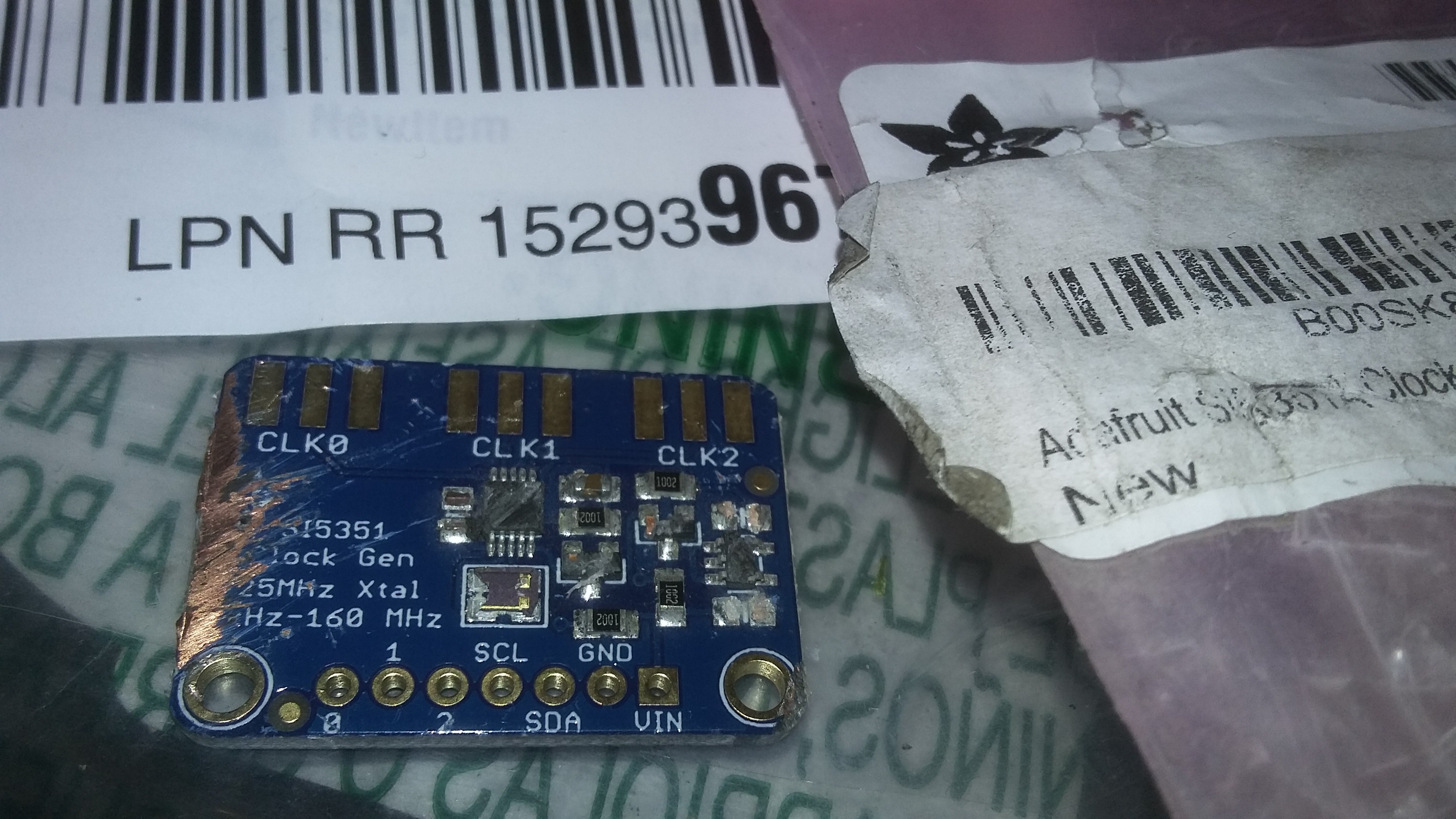
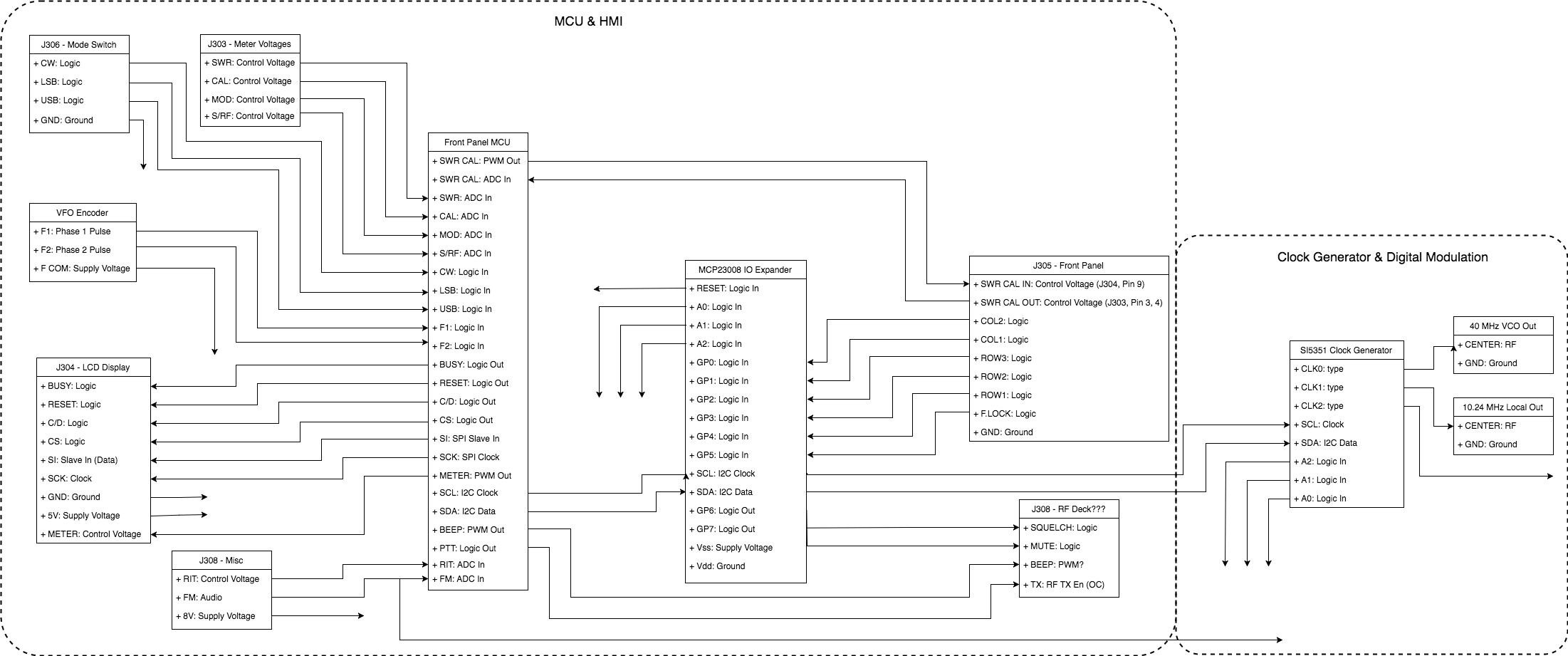
The clock generator for the alpha version of PB121 will be a SI5351 from Adafruit. These are available in large quantities cheaply and $7.95 in single quantities. It provides 3 clock outputs and is designed for RF PLL synthesis. I have used Silicon Labs ClockBuilder Pro to build a suitable Band Plan for the chip to generate all the signals needed to run the HR2510 RF deck. More info can be found in the overview of the Adafruit SI5351 Breakout.
More information on these radios can be found at:
- HR2510 http://www.rigpix.com/mischam/president_hr2510.htm
- Albrecht AE-485 http://www.rigpix.com/mischam/albrecht_ae485s.htm
- Albrecht AE-497 http://www.rigpix.com/mischam/albrecht_ae497s.htm
- Australia HR2510 - https://www.uniden.com.au/RESOURCES_MAIN/pdfs/HR2510.PDF
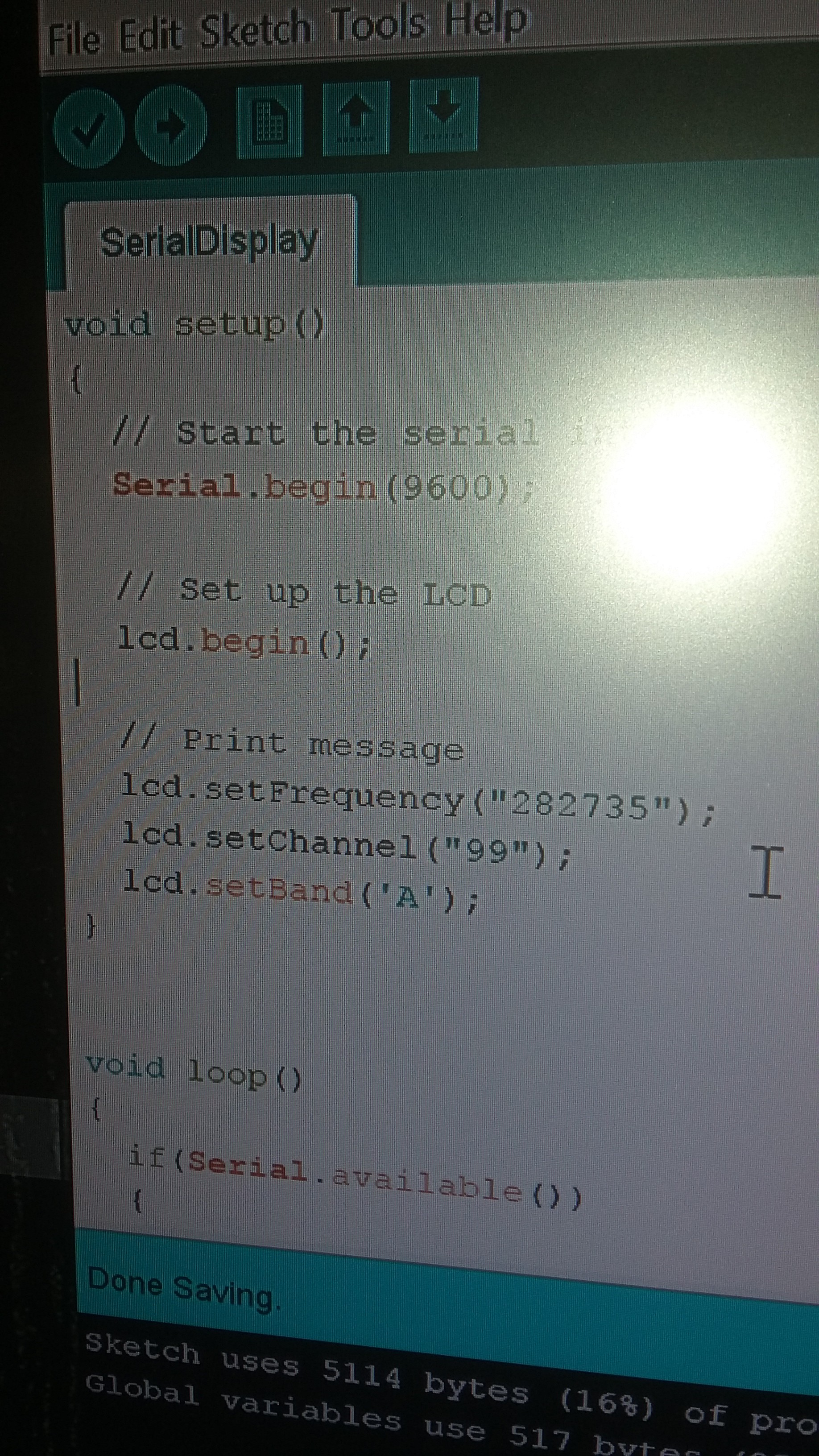 Pardon the crusty old HR2510 that has been beating around in the truck for a decade or so. But do notice that the above code is driving the display.
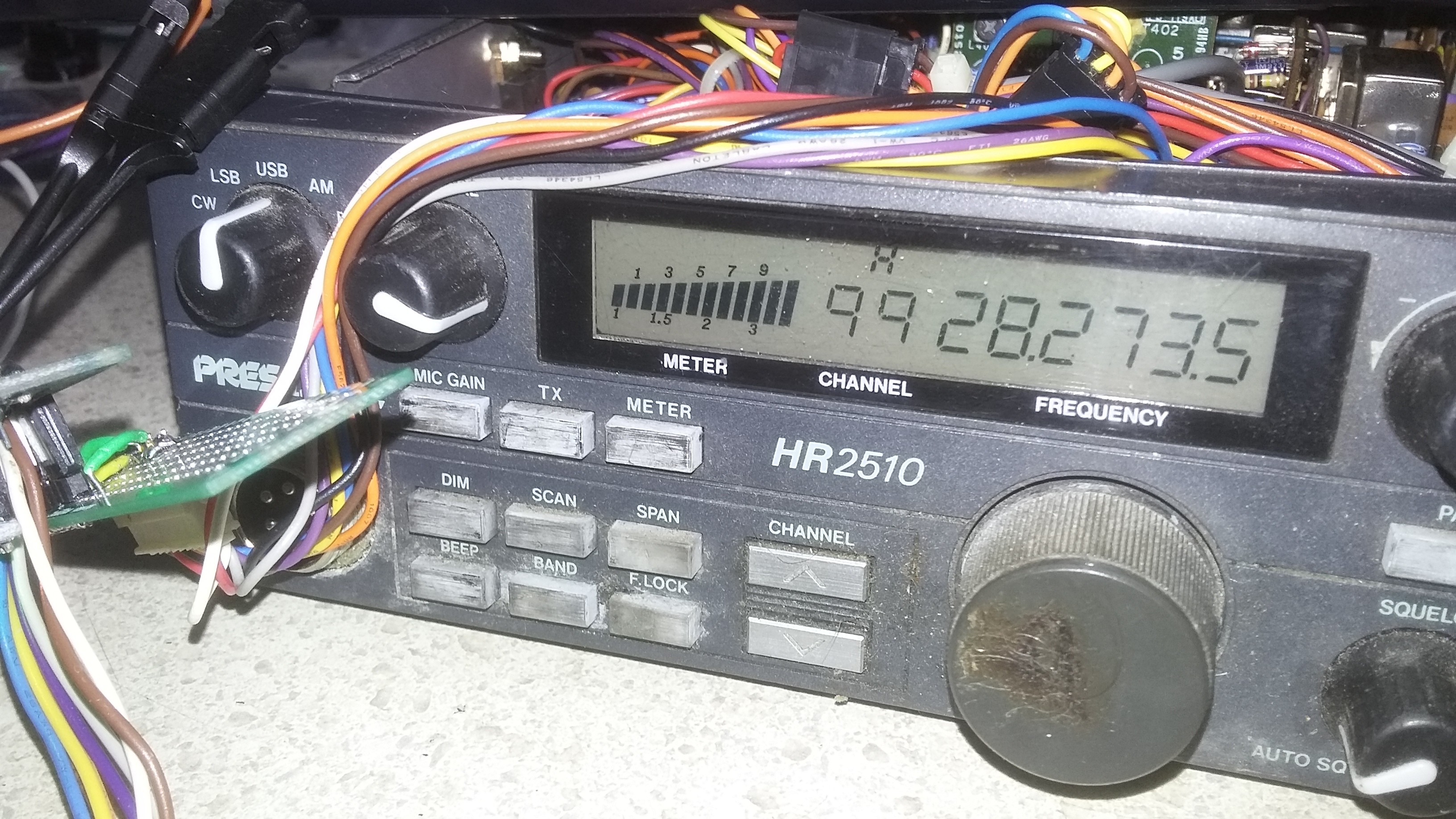

 Dimitar
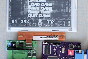
 PK
PK
 seasleyece