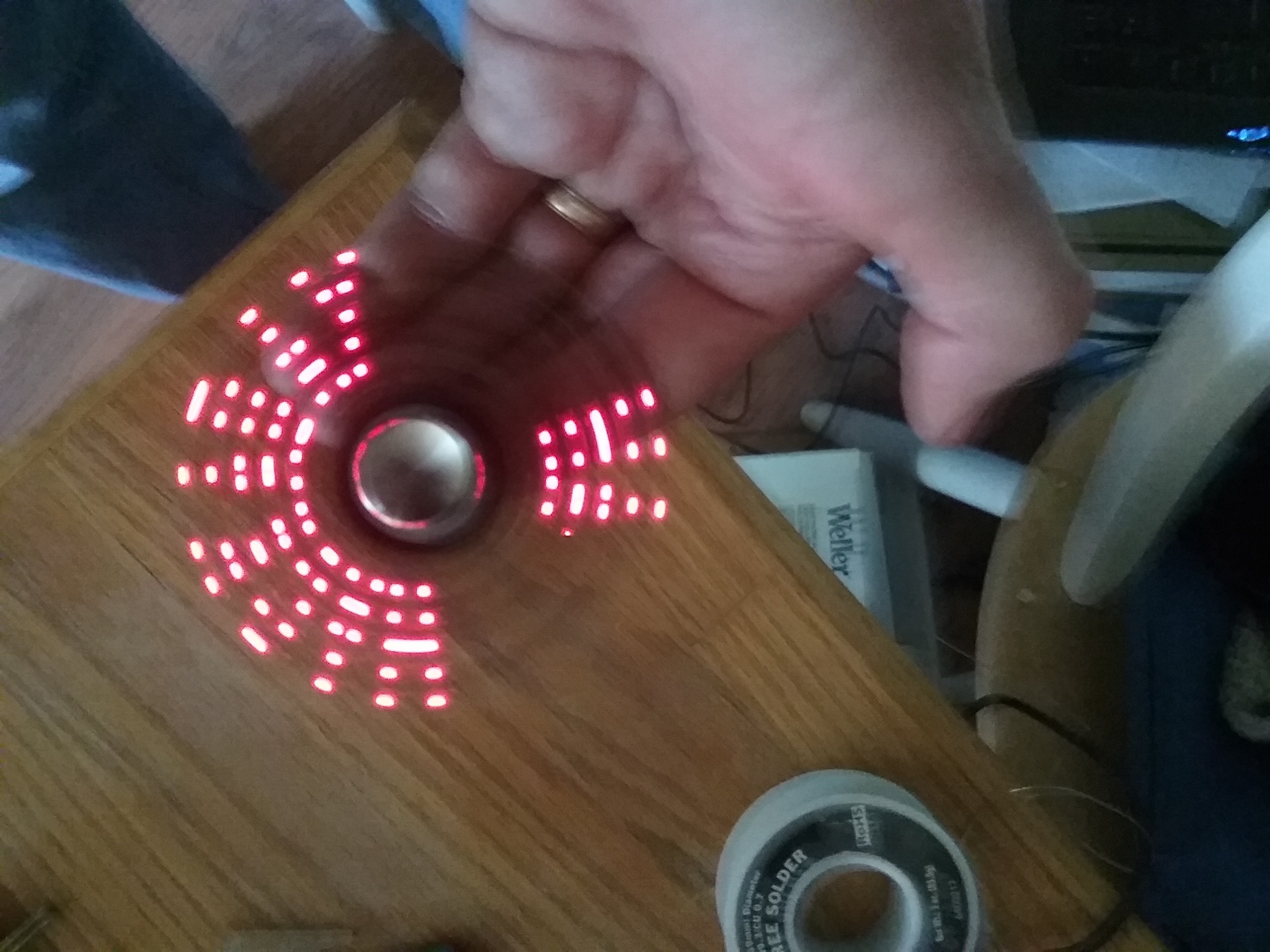
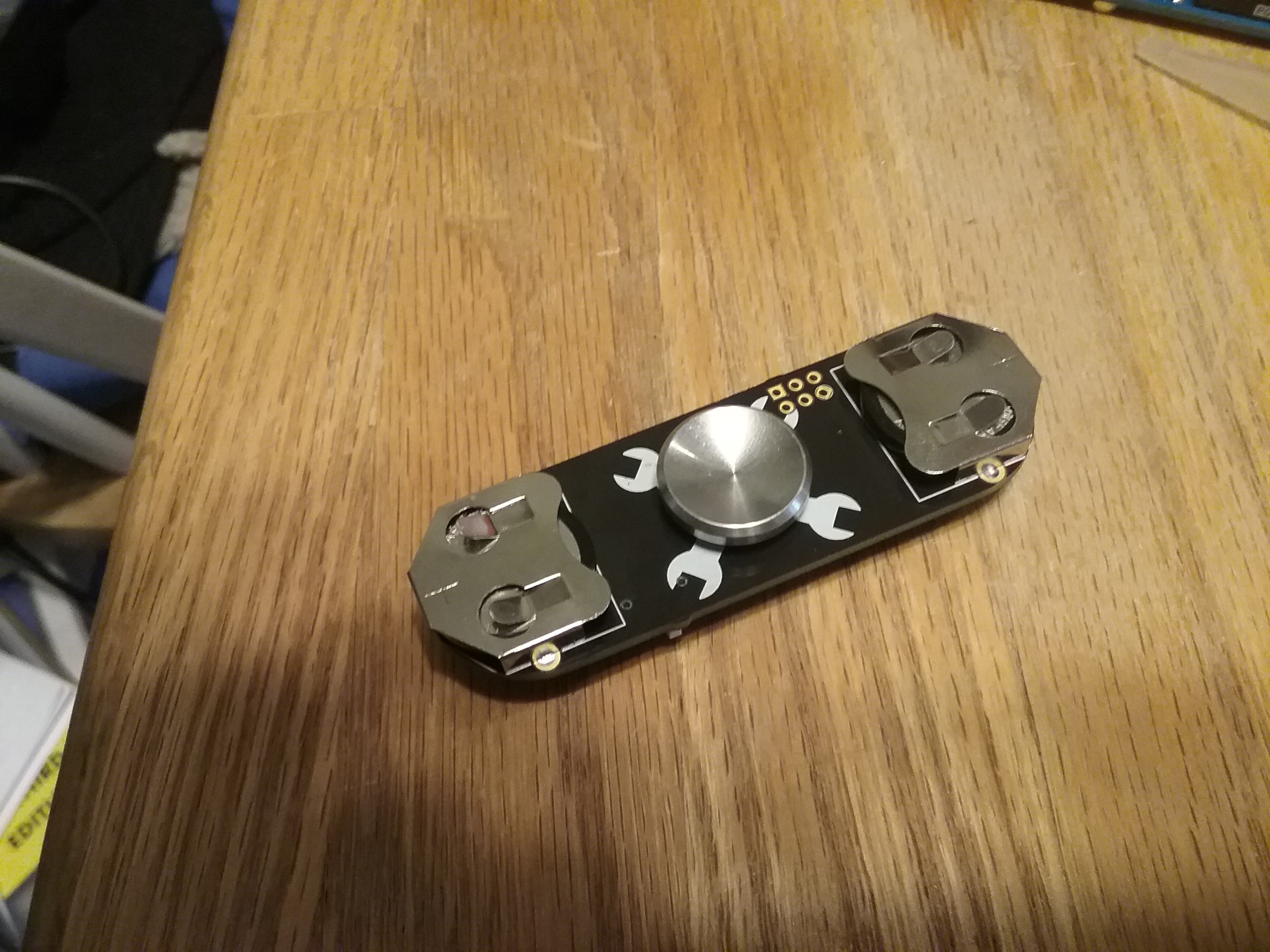
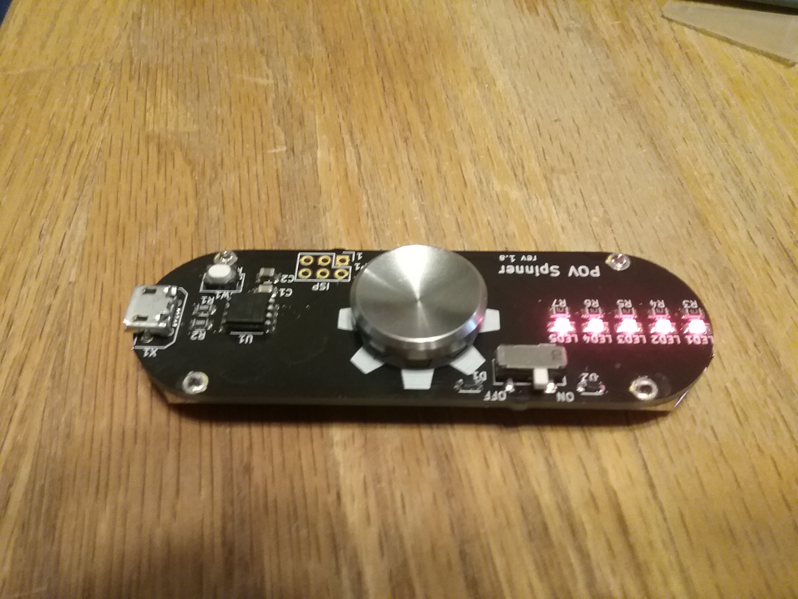
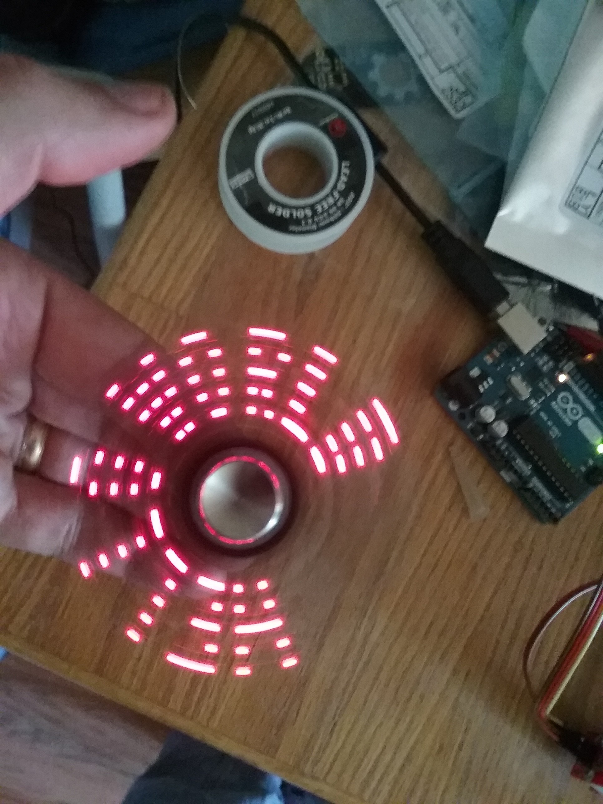
Although the most popular fidget spinners seem to be the ones with 3 sides, for this project I decided to go with a 2 sided design. A 2 sided design would enable me to use 2 cr2032 batteries wired in parallel for power, one on either side of the spinner. This would help to balance out the spinner nicely as well as provide enough current to power a small micro and the leds. For the microcontroller, I went with the AtTiny85, since it had a small footprint, a wide operating voltage, and fairly low current draw. I'm using the trinket bootloader to load sketches into the board via the usb plug.
In my original design, I used the popular 608 size bearing. This by far was the bearing of choice it seemed for most fidget spinners. I found though that using this size, left almost no clearance on the sides of the board for traces running to the leds. Ultimately I decided to go instead with the R188 size bearing since, measuring only 12.7mm diameter, it gave me far more clearance to route traces around. I also was able to leave enough clearance around this bearing to hopefully add a cap to make spinning a little easier.
Finally, the ultimate goal of this project was to make something that could inspire fun and learning in this new generation of kids obsessed with fidget spinners. I did this through the use of a simple design, that is both low cost and easy to assemble. This project can be constructed in its entirety in a one off project for as little as $15 total, including the bearings and pcb. All of the components are within the range of anyone to solder. And the schematic and design are easy for anyone to understand.
 Jon Thomasson


 Jay8ee
 Kumar, Abhishek
 Gee Bartlett
I would like to make this spinner.
Can you please share the BOM with the part numbers and package sizes and eventually link to manufacturer?
Thanks!
Eduardo