 Kumar, Abhishek
There was once a time when I used to build all circuits by hand (before PCB fabrication was as cheap as it is now), it was how I got into building circuits on the very venerable veroboards of 2.54mm pitch available in all shapes and sizes. Even when I started experimenting with SMT components (Nokia 6610 LCDs with 10-pin hirose connectors and STM32 microcontrollers), the very first circuits I built with them were using enamel wire. Of course it took a lot of time and patience to solder down the chips but it was extremely satisfying.
Today I see a trend of castellated sub-assemblies growing - both with lower cost devices (like the Pico and other small boards) and I have often felt that having tiny breakouts of fine-pitch SMT parts can help accelerate prototyping. They can be as complex as FPGA boards or as simple as a breakout board. However castellation imposes the constraint of them being on 2.54mm pitch to be able to solder them down on conventional perfboards. There are 2mm boards also available but less common. Folks may have tried unconventional veroboard designs but they haven't been scalable or widespread. Enter flexible PCBs.
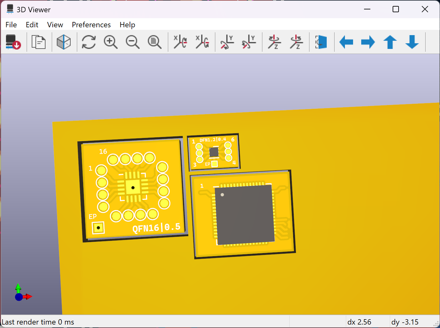
The pitch (pun intended) of this project is to build tiny breakout adhesive-backed pieces of flex in a panel with all possible SMT footprints of your favourite parts or stash (think 0603/0402 SMT, crystals, SOT, LEDs, QFP/QFN/BGA, WLCSP, DFN) with the pads brought out to hand-solderable yet tiny pads to enable rapid prototyping between the SMT parts once you cut out the pieces of flex and paste them down on a PCB like Lego(tm) blocks, and just have to use a soldering iron and magnet wire to wire up the stuff together. This could be ideal for uses where you may not be ready to build a PCB yet but want to try out the newest and fancy SMT part in the house.


 Michael Delaney
 newdrive
 Marek Więcek
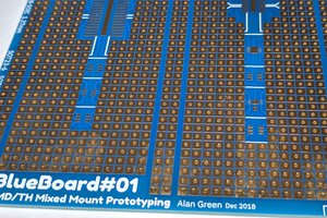
 Alan Green