 jflaschberger
From the electronics side, this project isn’t too complex, although the low power requirements are serious and everything should be as tiny as possible. The core functionalities that we need are
- Bluetooth low energy (BLE) connection to transfer data to a mobile phone or tablet
- Hall sensor, to detect spinning of the ferrite when liquid flows through (drinking)
- Microcontroller, to read out the hall pulses, do some math and tell the BLE module what to do
- Battery + voltage regulation
BLE modules can do more than BLE!
Coming from the Arduino world, the amateur hacker is always tempted to think in “modules” that one can attach to the core brain, usually a standard Arduino or derivate. In many cases, these modern modules are way more powerful that the used microcontroller itself and can fulfill its tasks with ease. The ESP8266 is a prominent example.
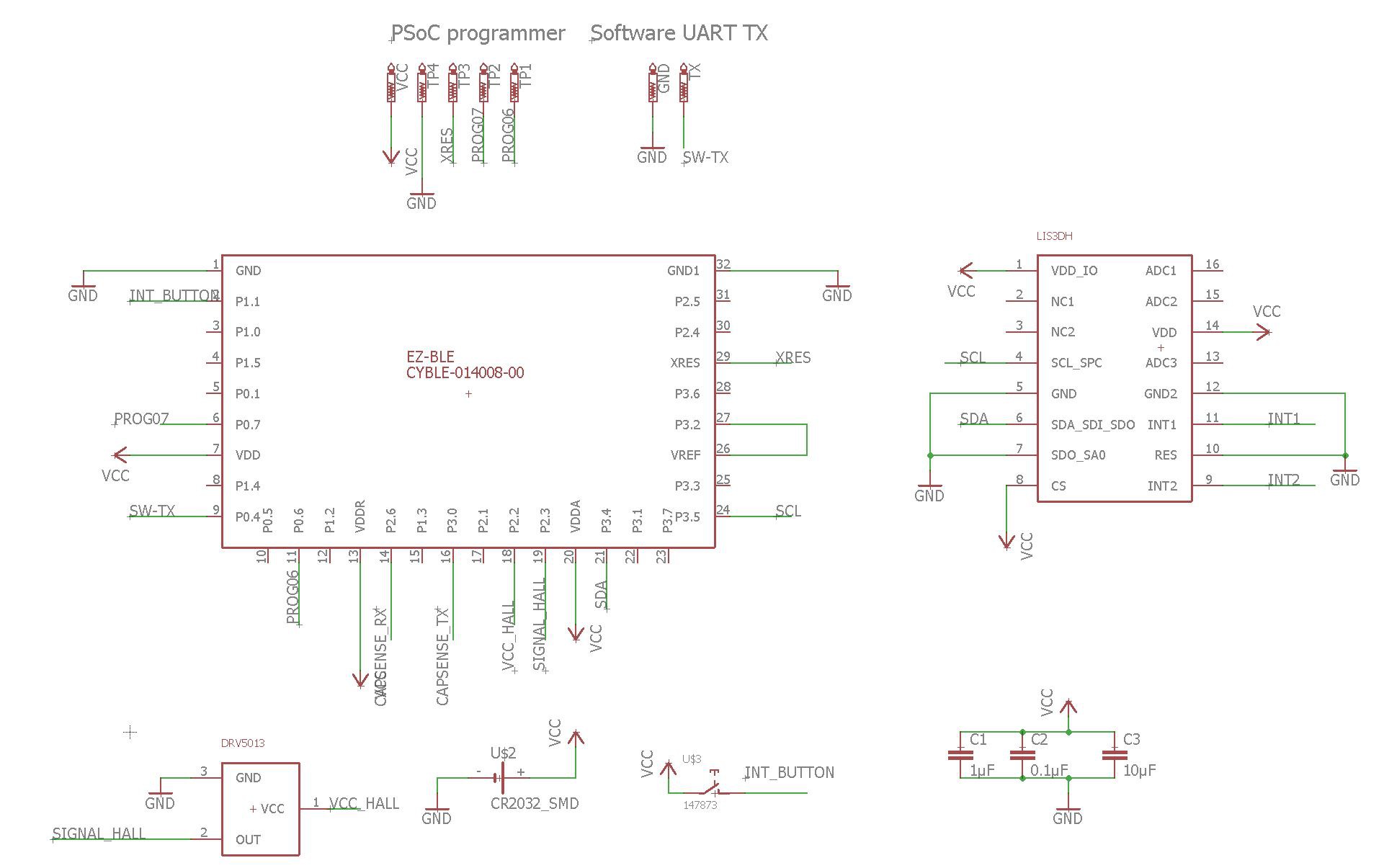
So: I chose an integrated BLE module from Cypress, a so-called PSoC4 BLE. PSoC stands for Programmable System on a Chip, it’s a successful microcontroller family with some programmable analog blocks inside, which make it possible to transfer some operations from the CPU to the analog blocks, making it very powerful for its price. The BLE version has an additional BLE-subsystem inside the package.
Cypress is selling this handy silicon as pre-certified module with all antenna-RF-stuff already neatly engineered on a micro-PCB, which can even be soldered by hand. Pre-certification saves us some 10k if we want to hit the market with this project as product without intense RF engineering to come. Oh, and for all who never left the Arduino-IDE: Cypress’ software PSoC creator is a well-documented, intuitive tool with tons of examples, so don’t be frightened. I’m not a Cypress fanboy, but absolutely enjoyed working with their toolchains in various projects.
A question of power
How should we power the device? If it is meant to be a consumer product, better use standard coin cells. The fact that the PSoC used is very tolerant to shifting voltage levels puts us in the luxury position, that we can skip the voltage regulation part and suck power from the battery directly. No regulator = no continuous losses = no low power problems = happy hacker. The battery we use is the standard CR2032 type, with a rated capacity of 210 mAh.
The other component which may eat up too much energy is the hall sensor. As the hall effect itself needs current to produce a detactable voltage, hall sensors are downwards limited regarding their power consumption. The one we use is already one of the low power ones, needing 2.7 mA on average. If always on, the hall sensor itself will eat up the whole battery in only 210 mAh / 2.7 mA = 77.7 hours. Solution: find a way to detect a drinking event and only power the hall sensor in this case. We don’t need a transistor for this, as the PSoC can drive the 2.7 mA directly.
Detecting a drinking event
The PSoC microcontroller family we use brings another feature which may come in handy:a predefined and tuned functionality to build touch-UIs (they call it “CapSense”): buttons, sliders, proximity switches. There is extensive documentation available, so I won’t explain it here. In short: it detects tiny changes in capacity without a physical contact needed, using very little power.
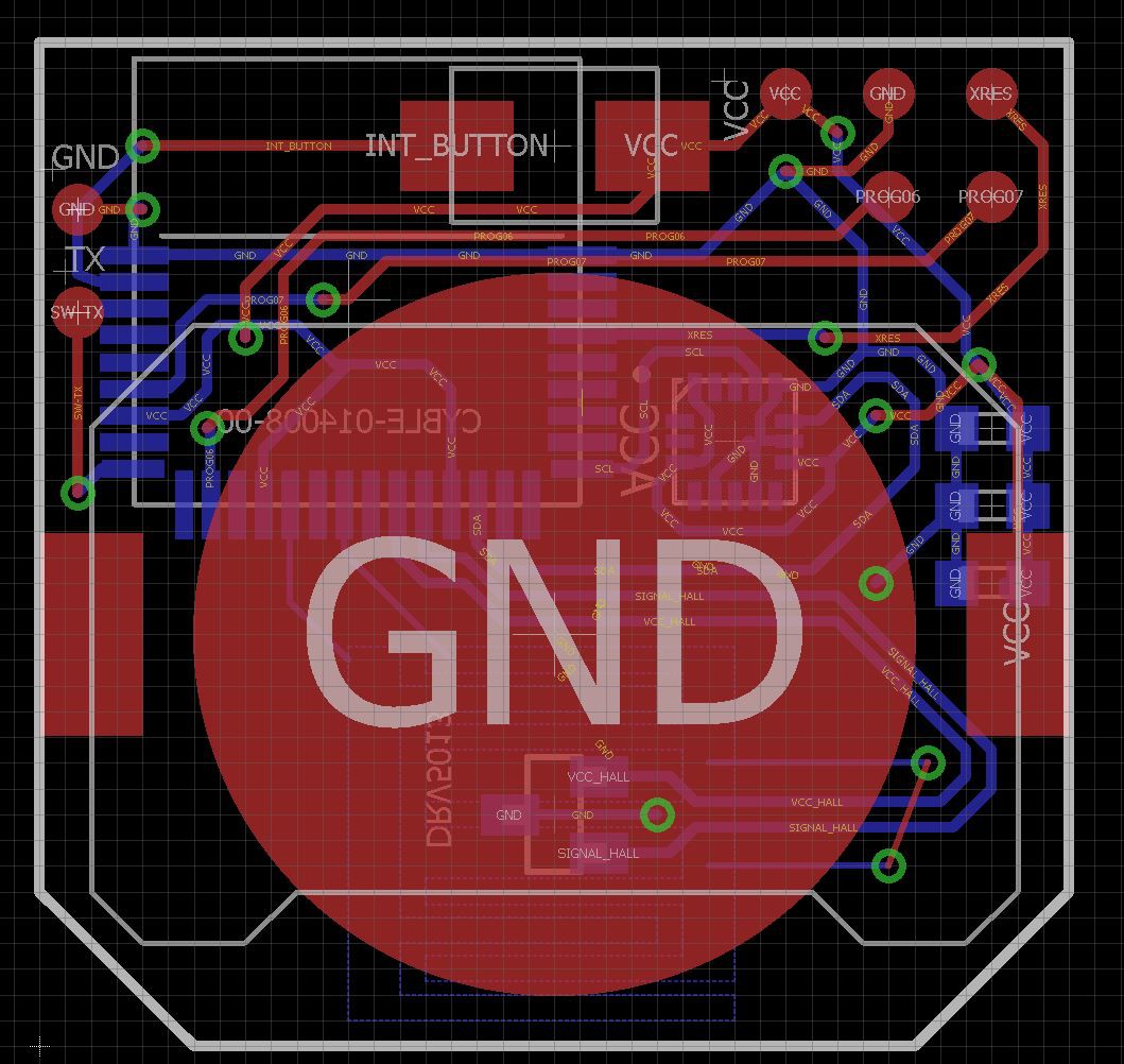
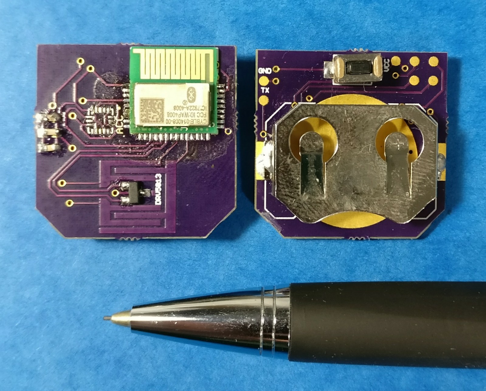
Hey, wait: in the previous passage we found out that we want to detect a drinking event in order to switch on the hall sensor. In other words: we want to get a trigger, if the canal within the mouthpiece fills with liquid. Maybe we can abuse a „touch button“ as a supercheap liquid detector? Of course, we cannot really stick to the specs of a decent touch button for the PCB, but let’s try. For this reason, you find the comb-like structures on the pcb. That is our touch-button aka liquid detector. Consult the CapSense documentation for further info.
Because I'm not sure about this, I added the footprint to a low power acellerometer to the pcb.
Interfacing
The PCB is too tiny to waste precious space with 2.54mm programming headers. Instead, I used custom pogo-pin pads. You will find them as fife golden circles on the pcb. Please refer to the build instructions for detailed documentation, pinout and build instructions. Of course, wires can be soldered to the pads for a more stable connection during development/debug.
“Oh god, it’s so tiny! How should I solder it?”
This is no problem, buddy! I managed to do so with ease with high quality OSH park pcbs, a hotplate (sold cheap as tools for mobile display repairs, search for "lcd separator") and low temperature solder paste, no stencil. Another prototype was soldered with a fine tipped iron completely. Please refer to the many great tutorials on soldering smd components that can be found around the web.
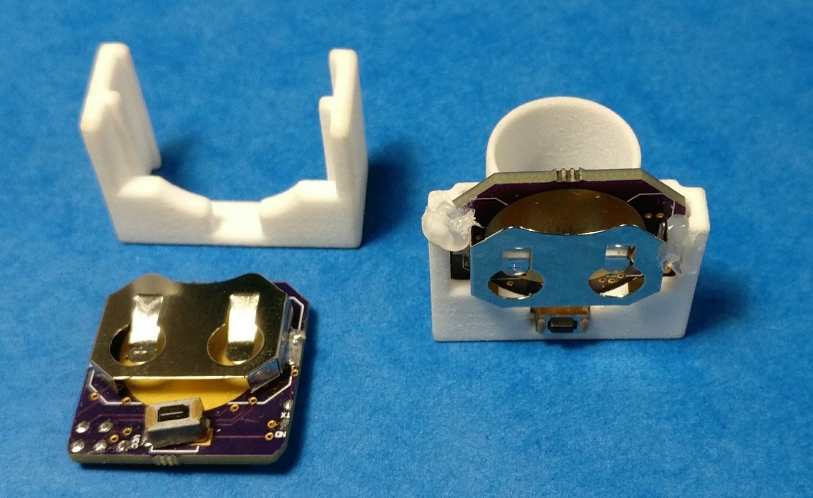
The pcb slides neatly into the holding bracket:
Discussions
Become a Hackaday.io Member
Create an account to leave a comment. Already have an account? Log In.