 Morning.Star
ESP8266, chips in a can
They are pretty little things and pack quite a punch even though the ports are limited. Only the two rows down the sides are free, and there are considerations.
After consulting with a couple of experts (Cheers @Arsenijs @david, @RoGeorge) I discovered I had a dead chip that refused to communicate although confusingly it did boot up. Apparently this is something of a lottery and other users have had failed boards so this is something to watch out for.
I bought mine as a Lua NodeMCU kit so I had the required pin-headers and a 3.3v Voltage Regulator as it uses lower power than standard TTL. I already have a USB USART to communicate with it. They are simple to use, so I thought it would be dead easy to do.
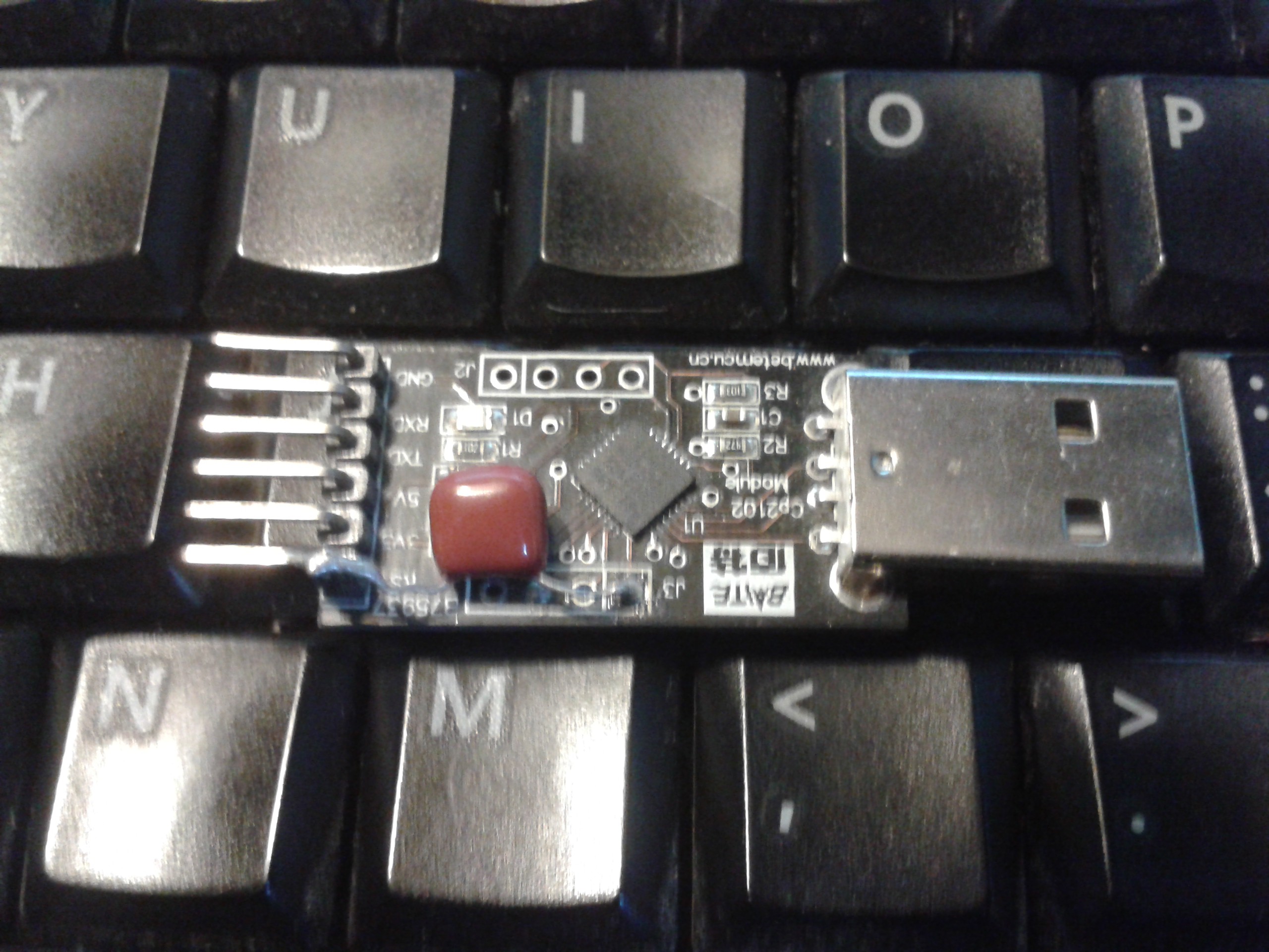
A Baite CP2102 USB USART. These things proved to be a nuisance when I bought them years ago. Although they supply 3.3v as well as 5v on the header, they wont drive a ESP properly and suffer from power supply issues although they will power an ATMega or similar which draws less current.
They also have the legend printed client-side, so the TX pin is labelled RX because that is what it connects to. It took a lot of swearing and eventually a scope to find this out, usually pins are labelled using the convention of what they actually are. And to garnish the plate, the 2102 USART doesnt carry the correct reset signal out of the chip, so I've cut a track and bridged the DTR signal that the host uses as a transport. DTR is a rising-edge signal, and the Megas use a falling edge on their reset line, so a small capacitor behaves as an inverter and pulls it low when DTR toggles. This is built into more modern chips but it's worth knowing.
ESP8266 doesnt behave the same as an ATMega
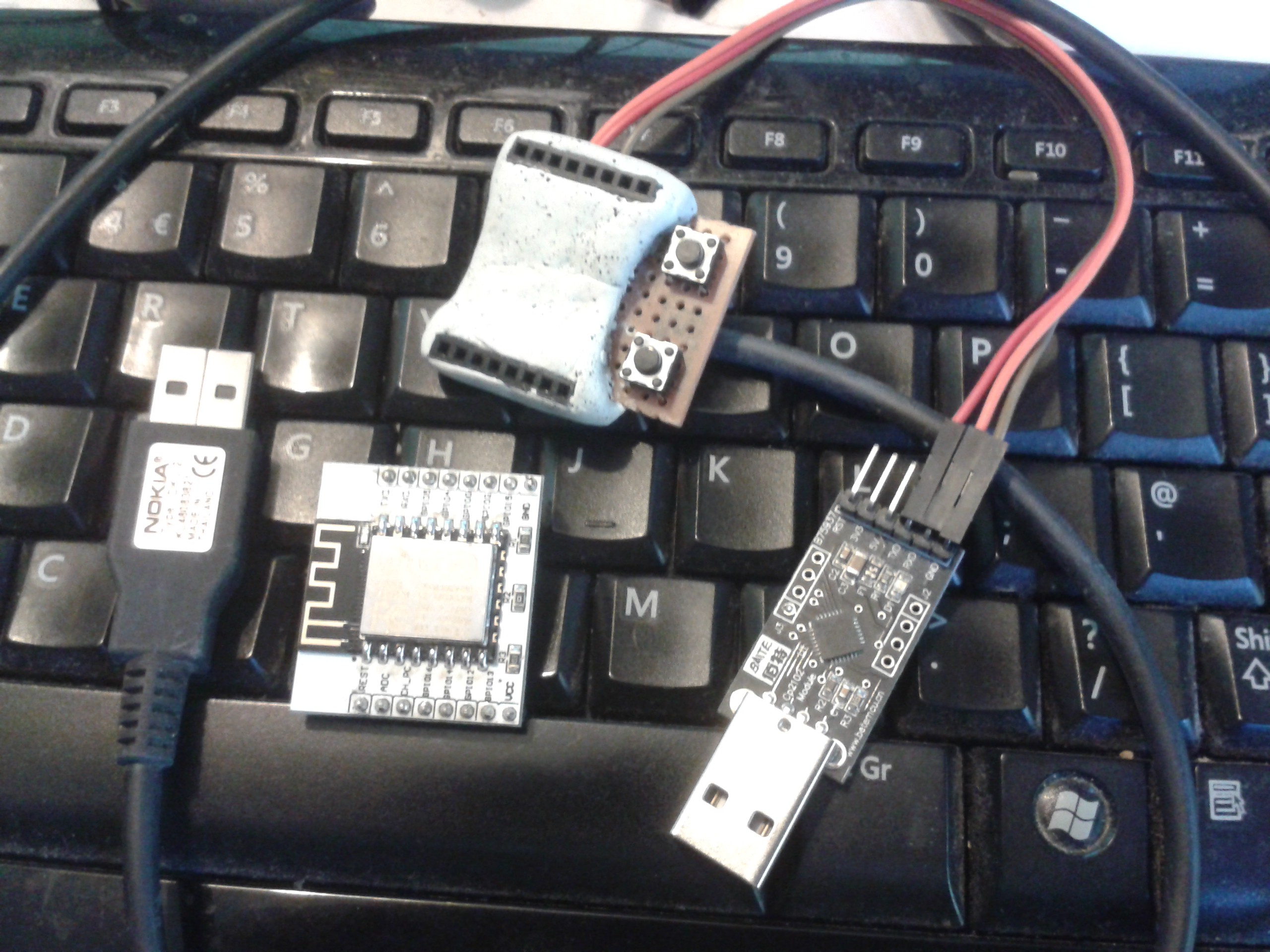
When a Mega resets using Arduino's software, the bootloader pauses and waits for a programming code, then boots the program stored in its memory if it doesnt get one. An ESP expects to have GPIO0 held down while it boots. This isnt easy to do, although its less of a lottery than trying to program a Mega without a reset signal. Again, Arsenijs kindly explained the obvious steps that you wont find on the internet unless you bought from Adafruit. They are hideously expensive and the delivery to the UK is extortionate as well, so I bought mine off eBay...
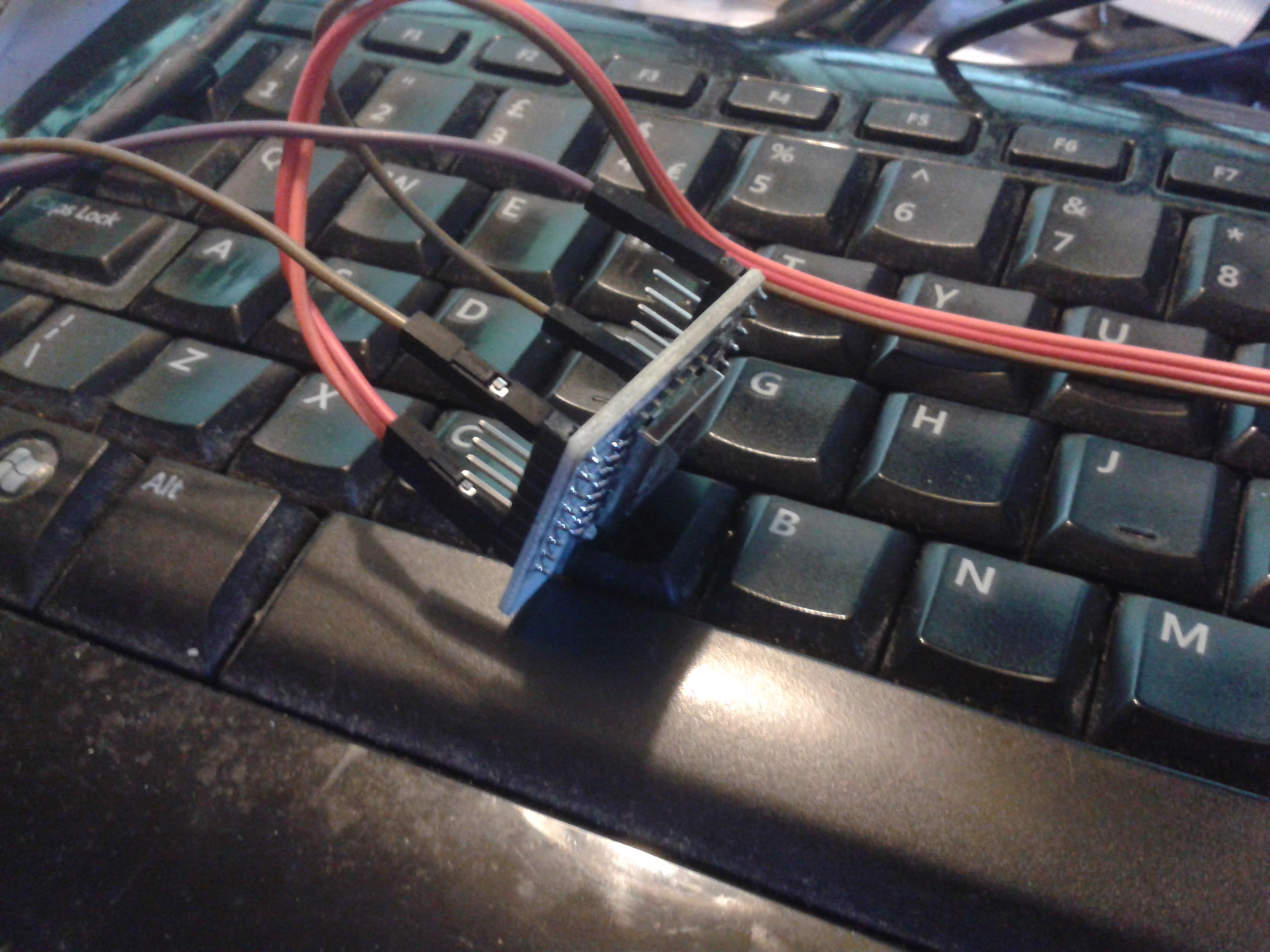
Trying to jumper the breakout board was a pain, so in the end I took a bit of strip-board and made a programmer from a cut-down IDE connector and a couple of buttons for RST and GPIO0. (Thats not Blu-Tack, its epoxy putty to hold the headers in place because the IDC connectors dont fit stripboard very well) To enter programming mode, hold down RST, then GPIO0, and finally release RST while still holding GPIO0 down. You only need to do this with Arduino, once MicroPython is installed it has a shell you can talk to to transfer software.
Finally
By now I was getting excited, after the dead board and all the messing about I finally got a heartbeat, I burned Blink on it, but the only LED is on the TX so I then tried the Serial examples from the Arduino IDE. Perfect, they all uploaded with no trouble at all and Lua was gone.
Next I downloaded MicroPython and burned that to the board following the instructions, and verified it worked in Arduino's Serial Terminal briefly but I didnt want to develop in that...
I loaded up CU, an ancient command-line terminal program that fell off the Unix wagon early on and I've been using ever since in Linux but for some bizarre reason all it would do is receive from the ESP. I tried carriage return and linefeed options, flow control and switched to plain ANSI but nothing made a difference. CU isnt very friendly, so I tried Minicom and that was the same. I also briefly loaded Python's Serial library which worked without trouble, but I didnt want to write a terminal myself.
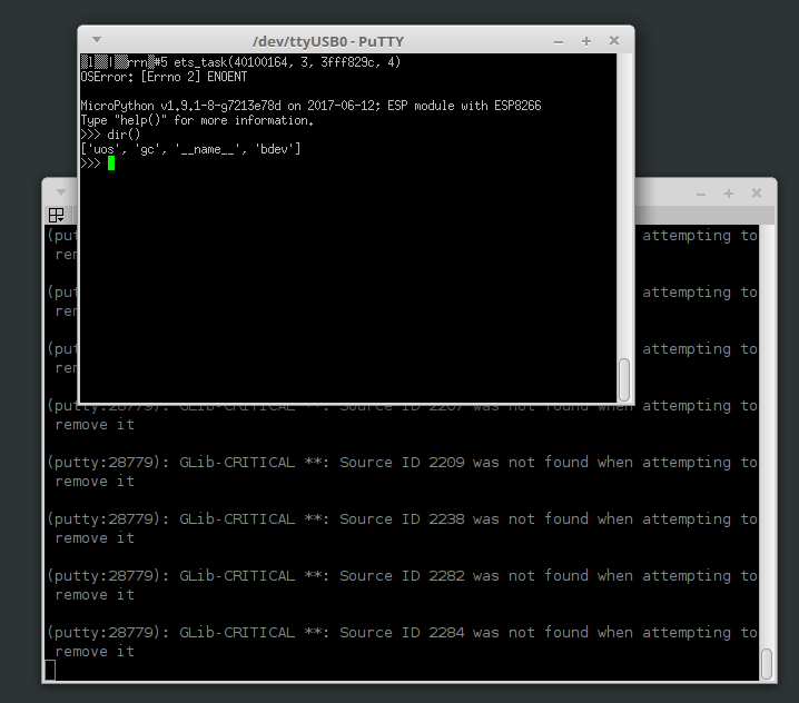
I found out from Putty that there's something hinkey with the transport layer in Linux that doesnt like the USB, but at least it worked even if it did complain bitterly about every character it got back.
Arsenijs then told me to try Ampy
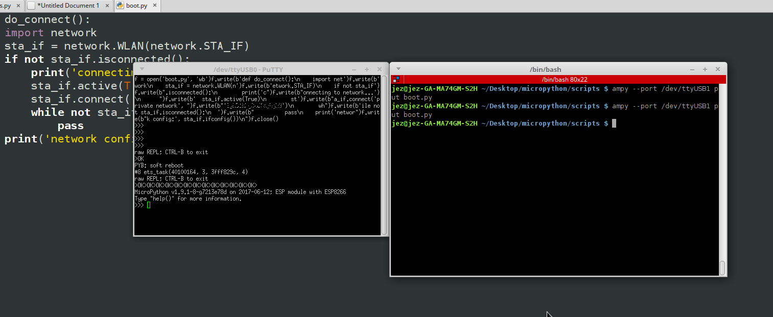
Sudo pip install ampyWhich downloaded and installed without error, but when I ran it complained that it couldnt find the executable. I blamed Adafruit for this, but it turns out
sudo pip install adafruit-ampyis the correct command to get the working version, and it loaded up a script in a matter of seconds once I tried it.
ampy --port /dev/ttyUSB0 run test.pyI was however a little suspicious of the amount of work I'd done to get here that used the same transport as Ampy so I determined to discover what the program was silently doing. I know enough about network systems to know that MicroPython woudnt contain any Adafruit code unless I put it there, so I wondered how it worked without a client on the ESP. If Adafruit could do it, so could I...
Even the old version of Arduino, which is written in JS and doesnt block the serial ports, wouldnt co-exist with Ampy so I could see what its doing so I broke out the electronic signals instead:
I added another USART to use as a slave, doubled the signal leads and then ran Putty connected to the USB1 slave while I ran Ampy on USB0.
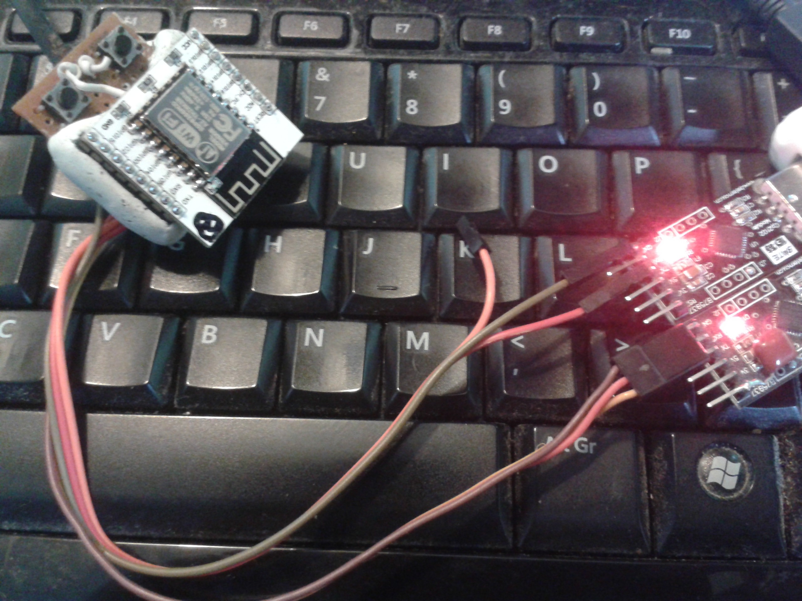
Here USB0 TX is connected to USB1 RX as well as ESP RX so I can see what is being sent. Next I swapped the leads over so the ESP TX drives USB1 RX as well as USB0 RX, and then I can see what comes back as well. I was expecting binary, but what I saw surprised me.
First of all, Ampy doesnt need a client. What it actually does is create a blind shell that talks to MicroPython's REPL, the console window that shows up on the serial host, and it pulls the same tricks as MicroPython provide for the user.
A 'CTRL-B' turns off the echo so you can paste commands directly into REPL in bulk but they still show up in the transmission stream and Ampy just silently hijacks the console and types for you.
Secondly, I'm not sure what all the secrecy is about, Adafruit are usually pretty good at explaining their stuff and could just as easily made a tutorial. If they did it doesnt show up in Google, but then neither did ampy, which returned like a million hits on a rechargeable battery instead.
And thirdly, why's this got to be so bloody difficult? I ordered two ESPs w/breakout kits from eBay and got one ESP, one breakout board and one voltage regulator, then a day later got a breakout board on its own. I complained and got another ESP and breakout but no regulator. SMD of course and the only TH regulators locally were 100mA. I'm building a sturdy regulated PSU with both 5 and 3.3v rails available... I have a 50% failure rate on the processors, had to outsource expertise and hack through something that smells like sophistry just to get going.
I hope some poor soul finds this information useful...