 Signals Everywhere/KR0SIV
The Details:
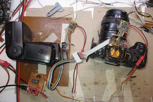
I bought this radio some time ago for weather alerts but no longer use it. It is on the chopping block and I've got a few plans for this little guy.
The Goals:
- Create an application to backup and restore the radio using the in-built cloning port
- Probe the port and see if I can talk to it for the purpose of dumping firmware
- Reprogram radio to support out of band ham frequencies to allow me to create a simple inexpensive radio for SKYWARN and ARES alerts... or you know, just fun shit like sending messages to a group. (radio uses SAME encoding which is well documented)
- Attempt dump and flashing of internal memory, possibly installing a teensy to allow flashing on demand and possible firmware modifications.
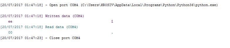 Serial port capture
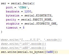 Python code snip
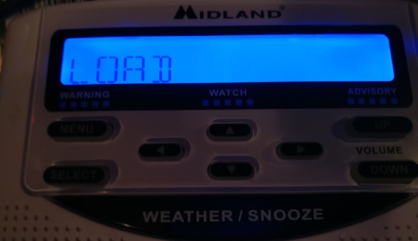
 When the UART is connected to the radio's RX pin it doesn't like to talk as much.
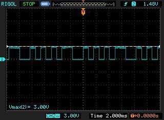
 Having a hard time guessing the baudrate
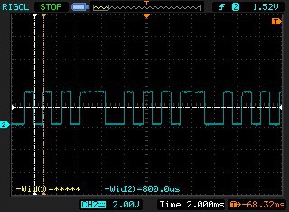
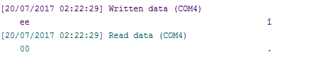
 Captain, we haz data!
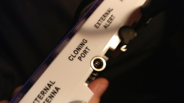
 Press < > at the same time during boot, press select when ready to send.
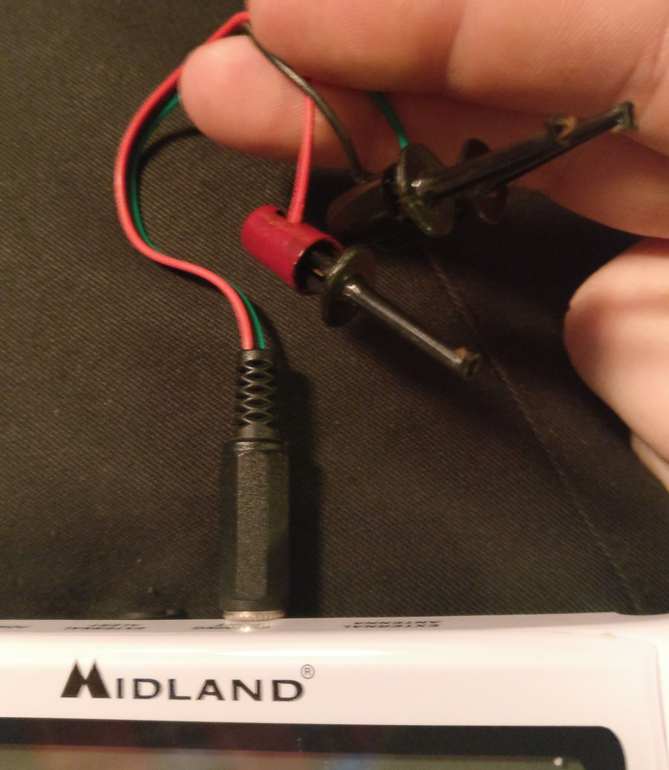
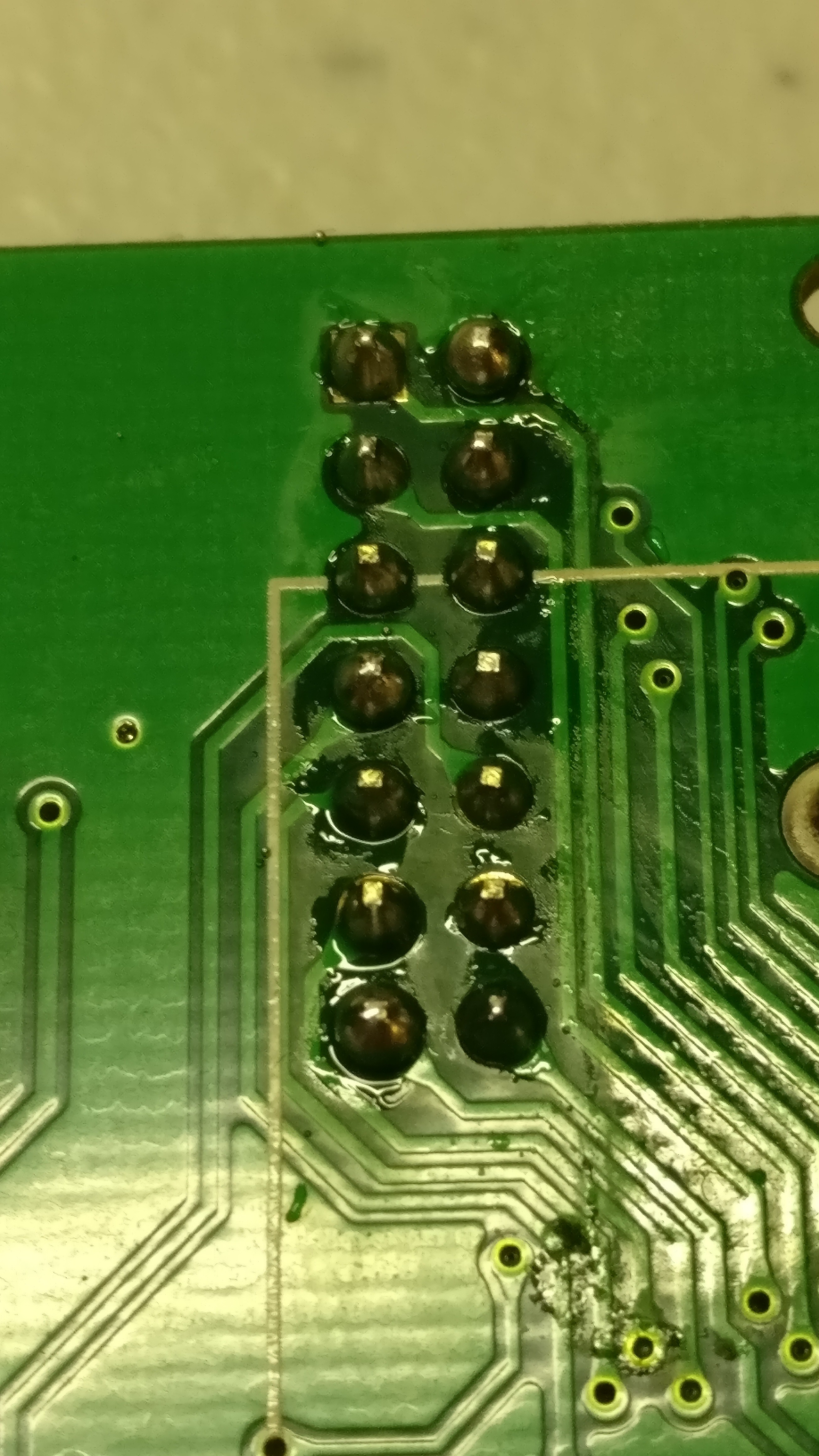
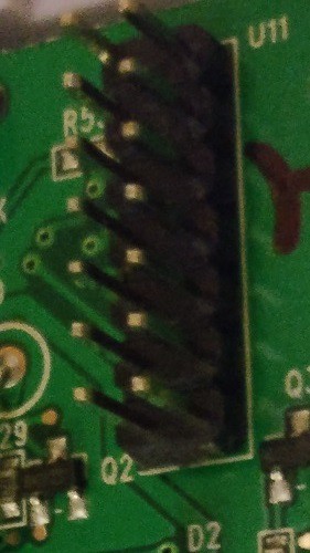
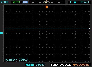
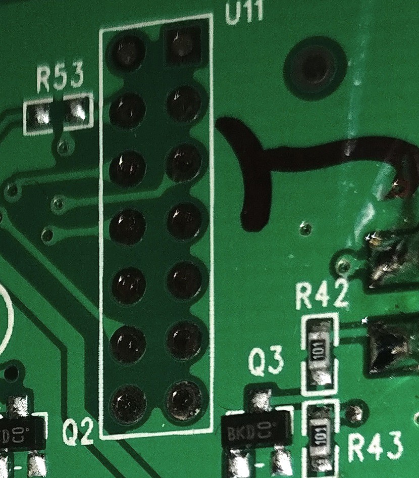
 Several Test Points but no other indications
 Test pads check voltage, no indication of data

 lion mclionhead
 agp.cooper
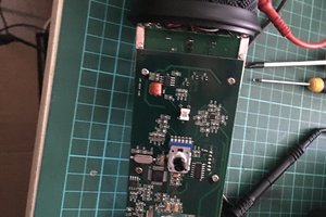
 Saabman
Excelente sigue así y lo lograras... quisiera ver como cambiar la alerta que tiene por fabrica y poner la que uno quisiera ...