 Roman
RomanThis project demonstrates a basic web application example with the CC3200 development board, AK9753, and TMP006 sensors (web-application link.)
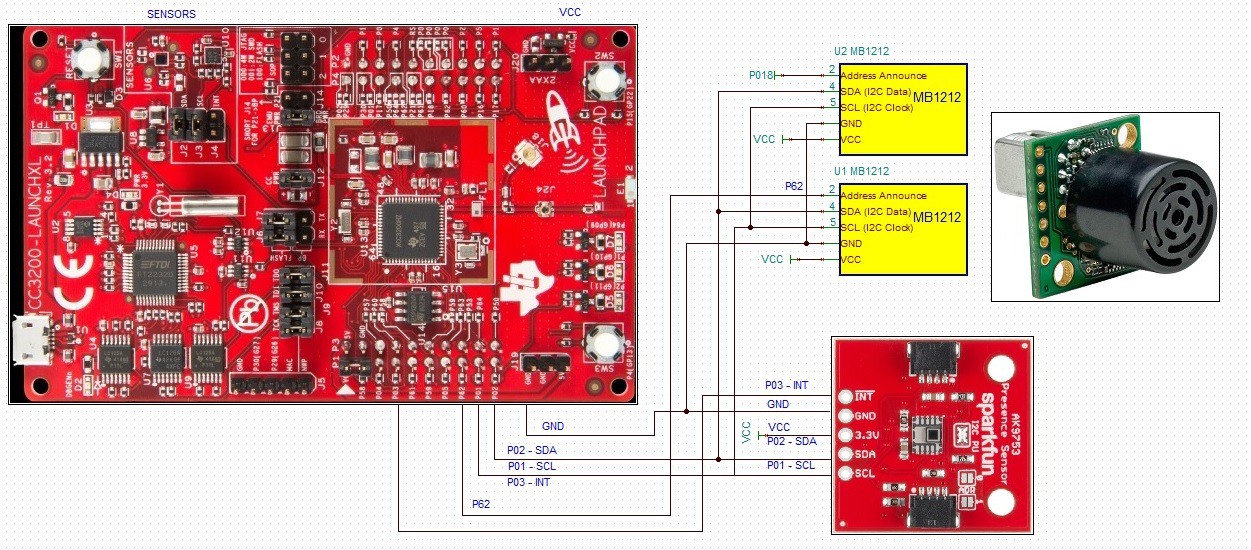
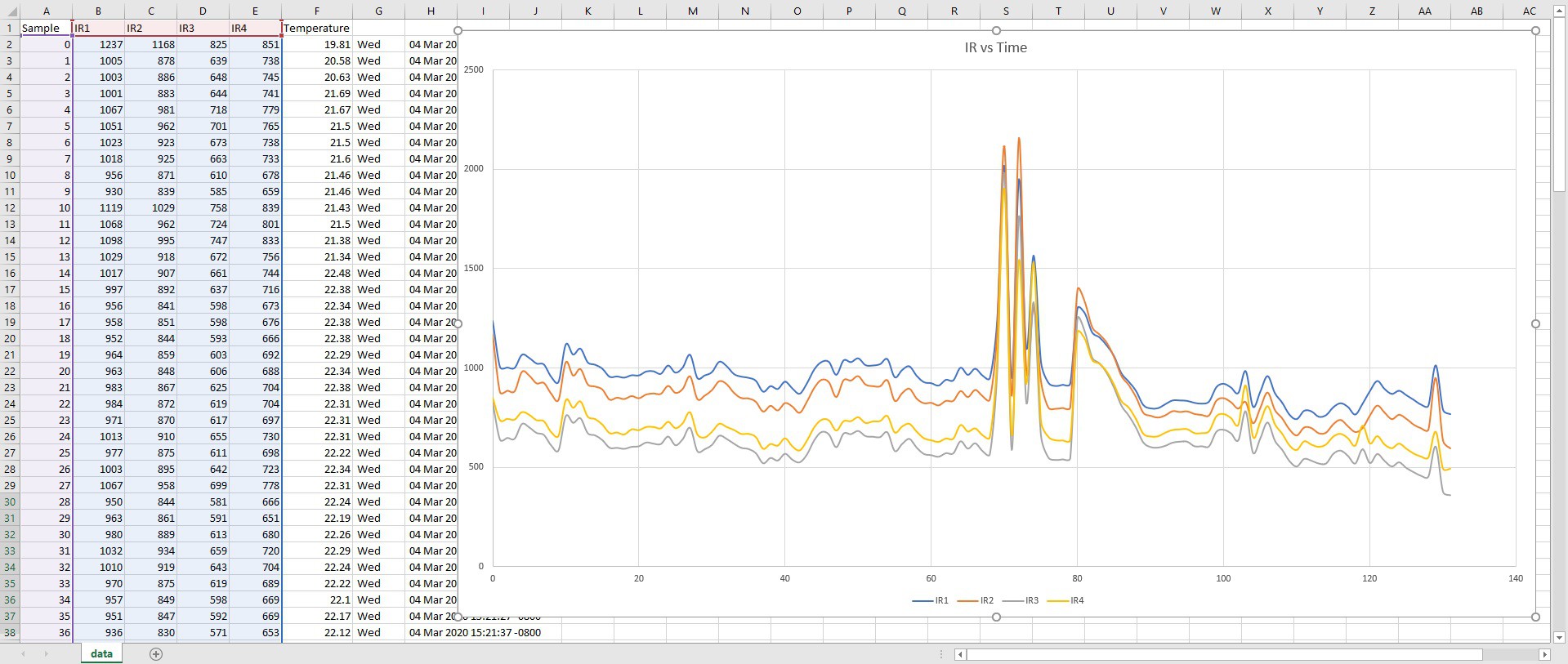
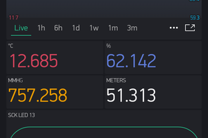
I have developed a simple web application for the CC3200 development board, an AK9753 Human Presence Sensor Breakout board , an on-board TMP006 sensor, and two MB1212 sonic sensors.
The web application displays data collected from all sensors and allows to switch (ON/OFF) the on-board Red LED. I am planning to add more functions to the web application.
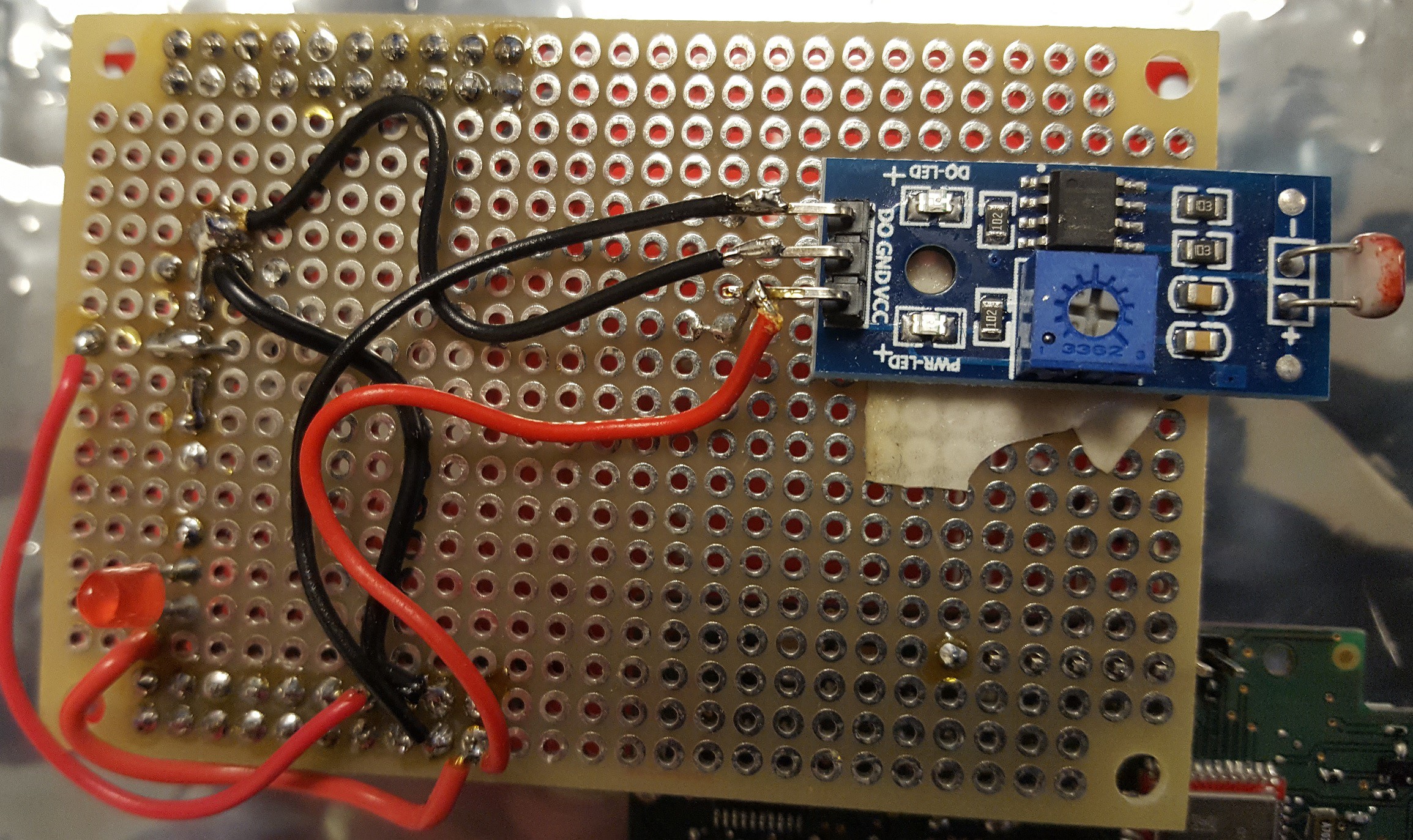
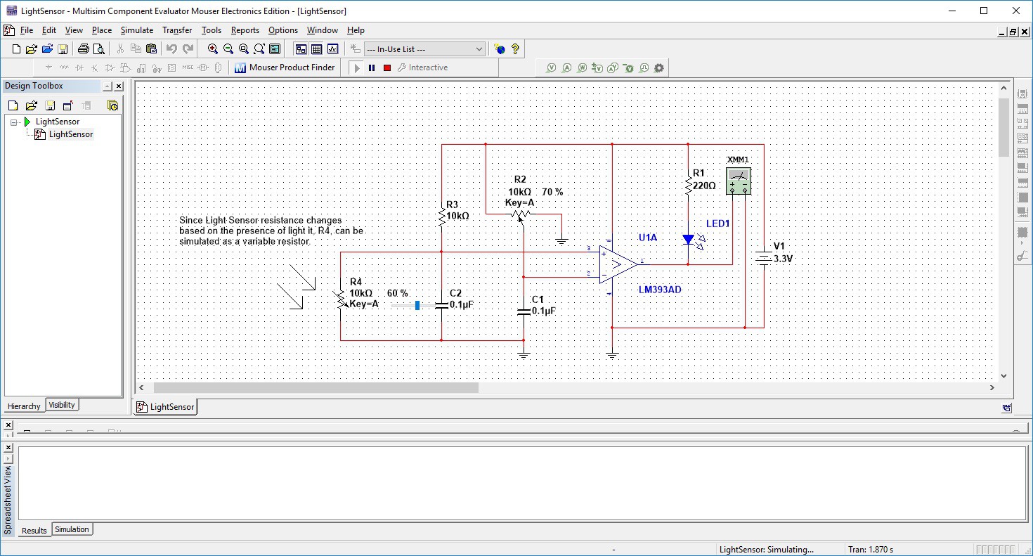
Show below is the image of my current circuit diagram. The MB1212 Maxbotix sensors will be used as motion sensors in the project.
To test the IOT project with your CC3200 development board:
- Download and install the CC3200 SDK on your PC.
- Download C-source code files from the Github. One of the files listed on the Github is a zip file of the CCS project (CC3200_client(CCS-project).zip). You can download and unzip the file.
- Import project files into your CCS workspace (link to CCS project import example).
- Connect CC3200 development board to a computer.
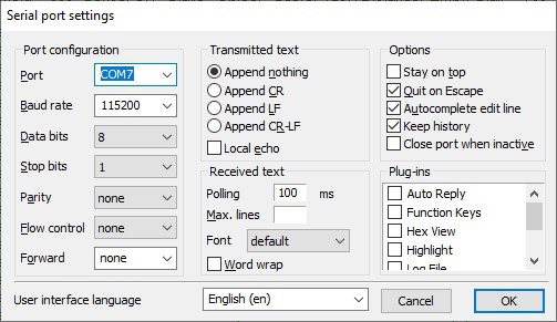
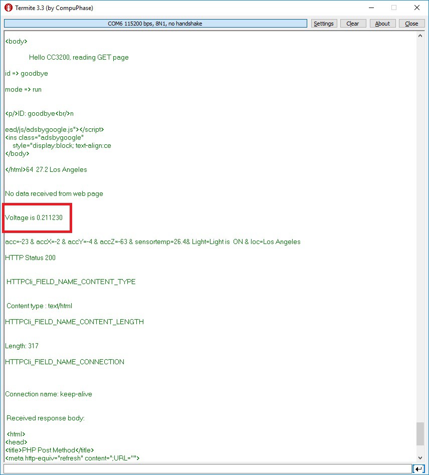
- Open a serial terminal on your PC and Set: COM PORT X, 115200 bps, 8N1, no parity, no flow control.
I recommend (it is not required) changing the MAC address from a default one. The MAC address will be used as a unique ID number to monitor data sent by your board. To set the new MAC address enter unique values as shown below. After the board is programmed you will need to press and hold SW3 and push the Reset button while pressing SW3. Afetr a 10 - 15 seconds you see " MAC address is set to: XX:XX:XX:XX:XX:XX" printen on a serial terminal:
//SET MAC address
GPIO_IF_GetPortNPin(SH_GPIO_13,&uiGPIOPort,&pucGPIOPin);//If SW3 button is pressed set MAC address
ucPinValue = GPIO_IF_Get(SH_GPIO_13,uiGPIOPort,pucGPIOPin);
if (ucPinValue == 1){
sl_Start(NULL,NULL,NULL);
_u8 MAC_Address[6];
MAC_Address[0] = 0x8;
MAC_Address[1] = 0x0;
MAC_Address[2] = 0x28;
MAC_Address[3] = 0x22;
MAC_Address[4] = 0x69;
MAC_Address[5] = 0x31;
sl_NetCfgSet(SL_MAC_ADDRESS_SET,1,SL_MAC_ADDR_LEN,(_u8 *)MAC_Address);
sl_Stop(0);
UART_PRINT("\n MAC address is set to: %02x:%02x:%02x:%02x:%02x:%02x \n",
MAC_Address[0],
MAC_Address[1],
MAC_Address[2],
MAC_Address[3],
MAC_Address[4],
MAC_Address[5]);
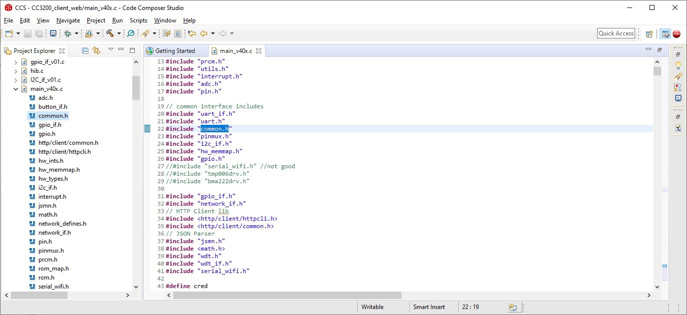
}Enter your WiFi credentials (SSID name and password) in the common.h file:
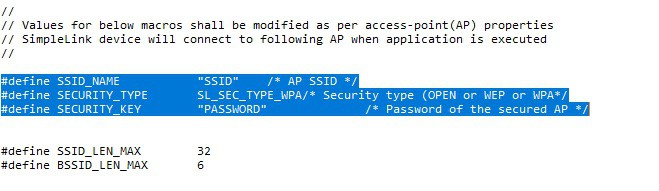
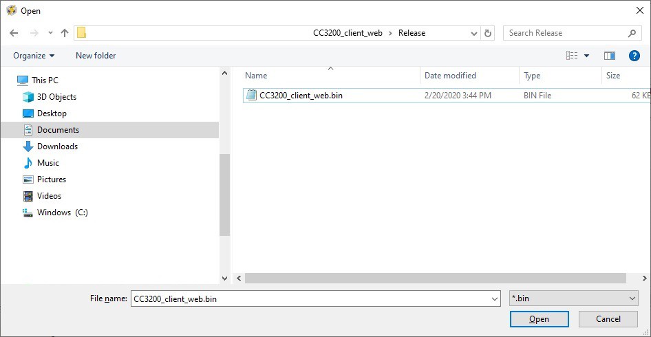
Save your project with the new credentials and compile it.
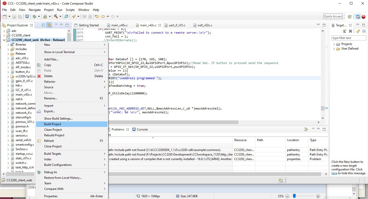
Once the project is compiled the "CC3200_client_web.bin" will be located in the Release folder:
- Program the CC3200 board with the CCS uniflash.
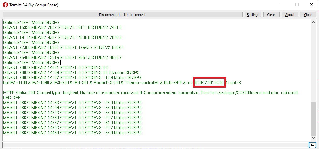
- If you want to change the MAC address from the default one, press and hold SW3 and push the reset button. Keep SW3 pressed untill the new MAC address is set and printed. This may take 15-20 sec
- Write down the number shown below. This is the ID number of your board. You will need it to display your data on the web-page. Conver the HEX value to a decimal and enter it on the web-app page as the ID number:
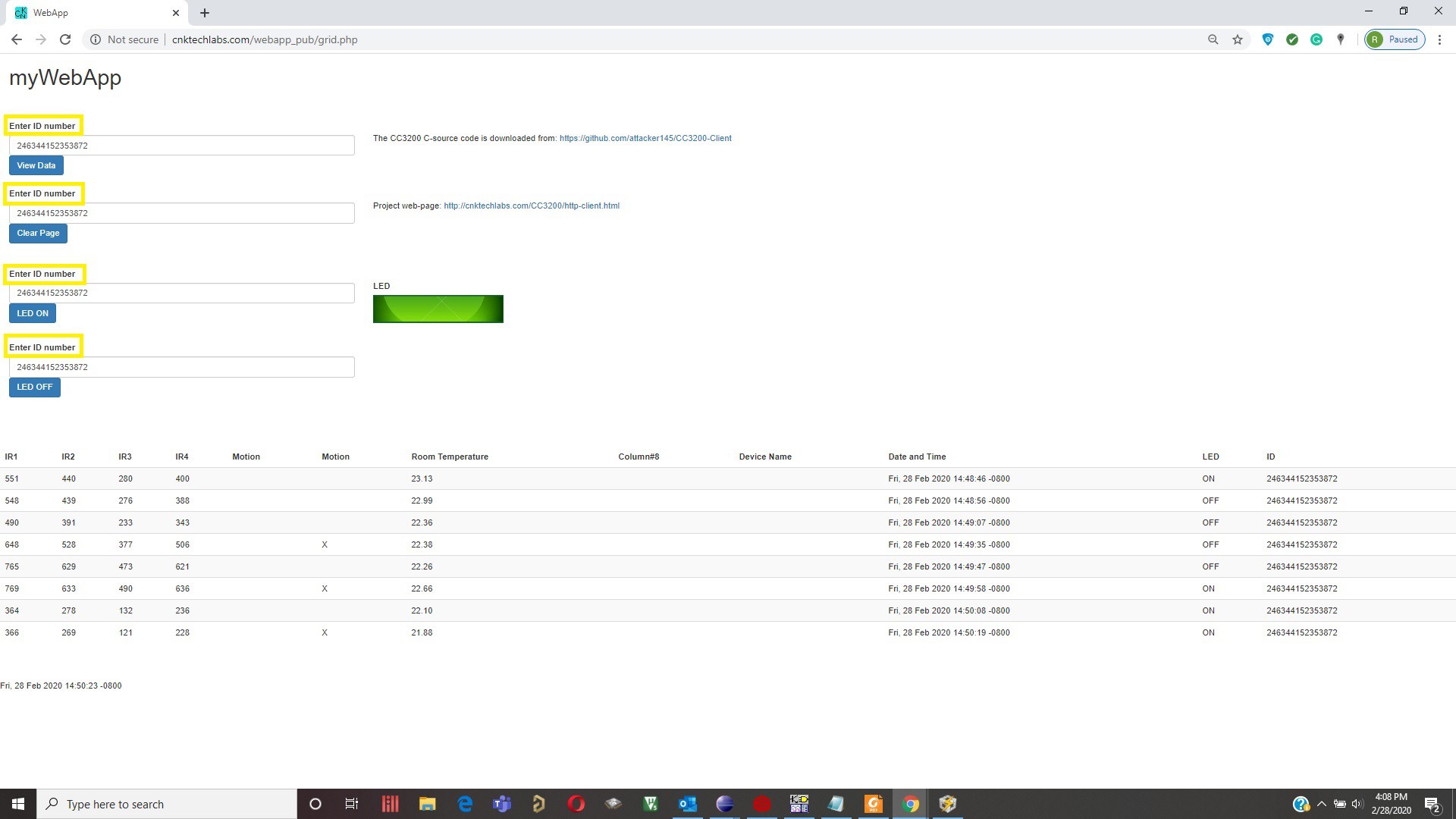
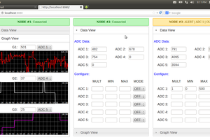
Monitor and control CC3200 board from cnktechlabs.com/webapp_pub/grid.php.
Enter the ID number in a decimal format:
How the data is transmitted and received over the web:
In the main file there are two functions:
- HTTPPostMethod_data(&httpClient);
- HTTPGetPageMethod(&httpClient);
that are used to transmit data to, and receive from the grid.php webpage. The first function posts data to the grid.php web-page approximately once a minute.
if(t_cntr > 250){//285 ~60 sec
    if(cnn_fail == 0){
        t_cntr = 0;
        lRetVal = HTTPPostMethod_data(&httpClient);//Post data to the grid.php
        if(lRetVal < 0){// If failed post data to the web-page
            f_cntr++;
            UART_PRINT(", Failed Post Method");
            EnterHIBernate();...
Read more »
 Amine Mehdi Mansouri
 Jaspreet Singh
 Alan
Alan