 Yann Guidon / YGDES
Spoiler alert : read the bottom of the page first :-D
This post is more or less totally not related to CPU design. It's absolutely related to power supplies however !
Let's just jump to the conclusion :
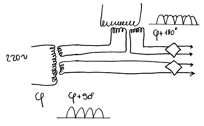
It's a particularly "overkill" "solution" to an old problem because it requires 2 identical transformers with dual outputs and could in theory output as much current as one.
The advantage is the reduced ripple and a much better cos φ because current is drawn from the mains during the 4 quadrants, instead of only 2. The output ripple is also reduced (and that's the whole point of this circuit ! ) and this is significant for certain types of loads.
The long story :
I finally received one TSL 40/001
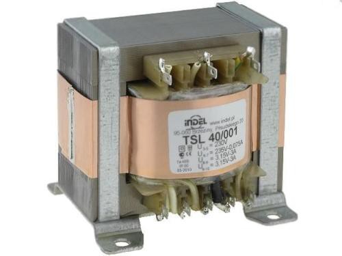
This little Polish device is a well built transformer, usually targeted at lamp/valve amplifiers with 3 secondaries : one is a low-current high voltage output, that I will ignore. The other two are 3A 3.15V, with 18W cumulated power. See the end of 43. Data retention times of hysteretic relay latches for more computations.
I bought one, that I never received. Then I bought a second that I received so I'm considering the next steps. But what if I received the first one ?
Using 2 transformers in parallel will not change much because they would be in phase and they both will require a large amount of filtering capacitors to keep the output ripple low.
Then I realised that the key was the dual, symmetrical but independent outputs. Usually you can wire them to either provide more current (in parallel) or more voltage (series). Or you can power a different circuit. But I have never tried to use the secondary as an isolation transformer, or a de-phaser, though in theory nothing prevents it.
In the above diagram, I use one secondary to de-phase the other secondary by 90°. Because the windings are identical, there should not be any mismatch and the "direct" secondary could be dampened with a small rheostat to account for the extra resistance in the de-phaser. 2 diode bridges rectify the output and only one of them is "active" at a time (one pair of diodes for each quadrant).
This is not as efficient as 3-phase power but it is totally what our grand-dads would have done if they could.
I'm curious to know if this had been already done before. It look like this kind of circuit should be in some textbooks but I have never seen them. The closes I've see is a very large inductor in front of a PSU to smooth and correct cos φ but 2 transformers ?...
I'm happy because this is a question that has been spinning in my head for more than 2 decades and I couldn't resolve myself to "using larger filtering capacitors".
...
Has anybody here seen this circuit before ?
@Bharbour notified me that this wouldn't work and he provided a 'scope screenshot.
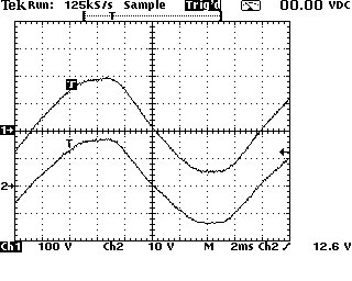
I'm very surprised because this goes against my understanding of how a transformer works.
So I tried too.
And I find no phase shifting either ! The output mostly copies the input.
I'm so disappointed :-D
Discussions
Become a Hackaday.io Member
Create an account to leave a comment. Already have an account? Log In.