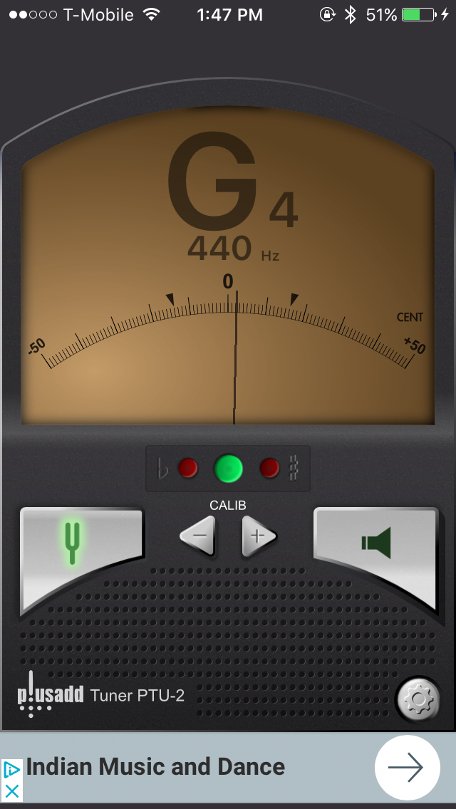
Automatic Tuner that reads sound waves and converts to mechanical movement.
0%
0%
Automatic Ukulele Tuner
Choose a note, Pluck a string, Let the device do the rest.
Become a Hackaday.io member
Already have an account? Log in.
Just one more thing
To make the experience fit your profile, pick a username and tell us what interests you.
Pick an awesome username
hackaday.io/
Your profile's URL: hackaday.io/username. Max 25 alphanumeric characters.
Pick a few interests
Projects that share your interests
People that share your interests


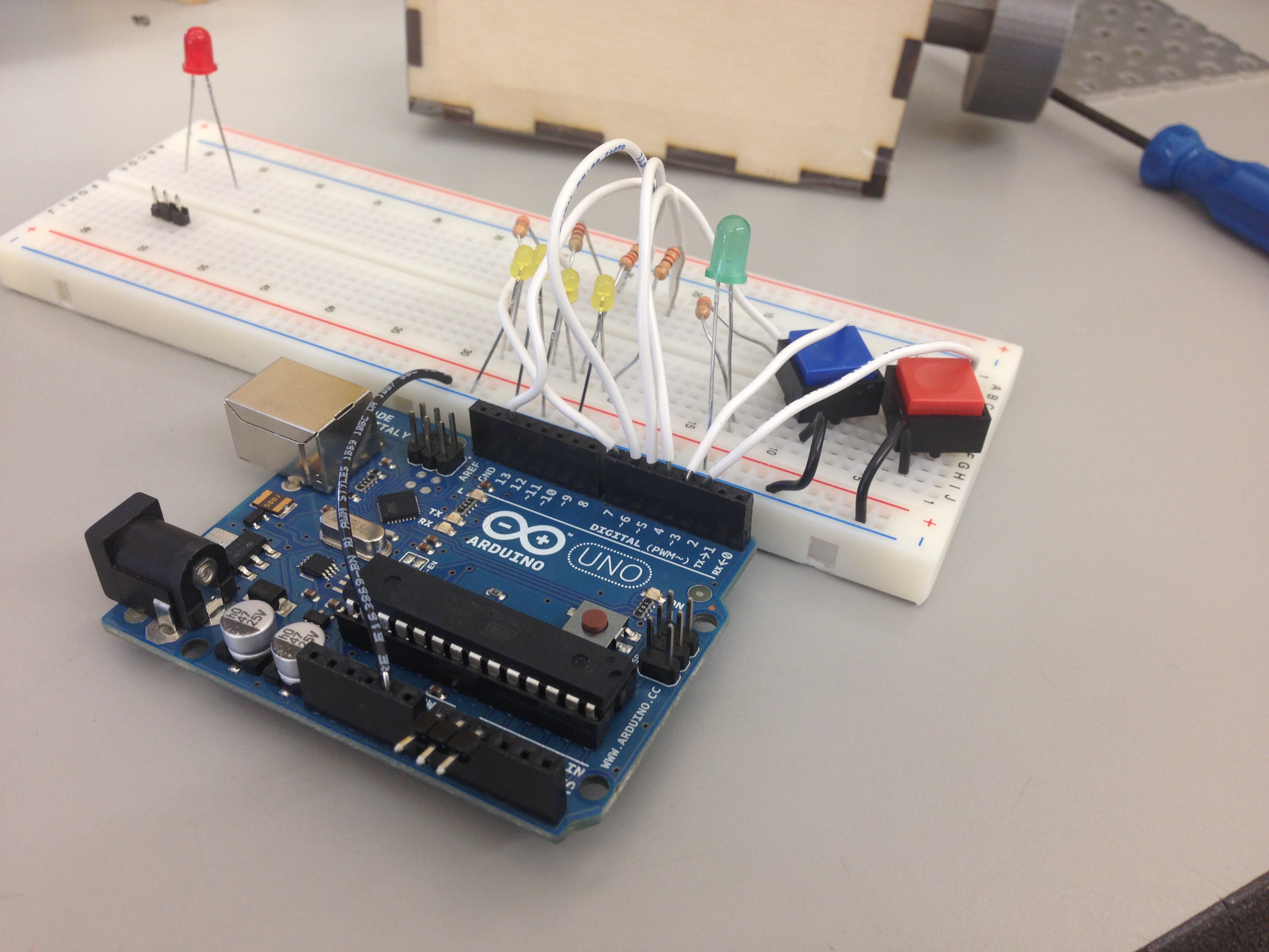
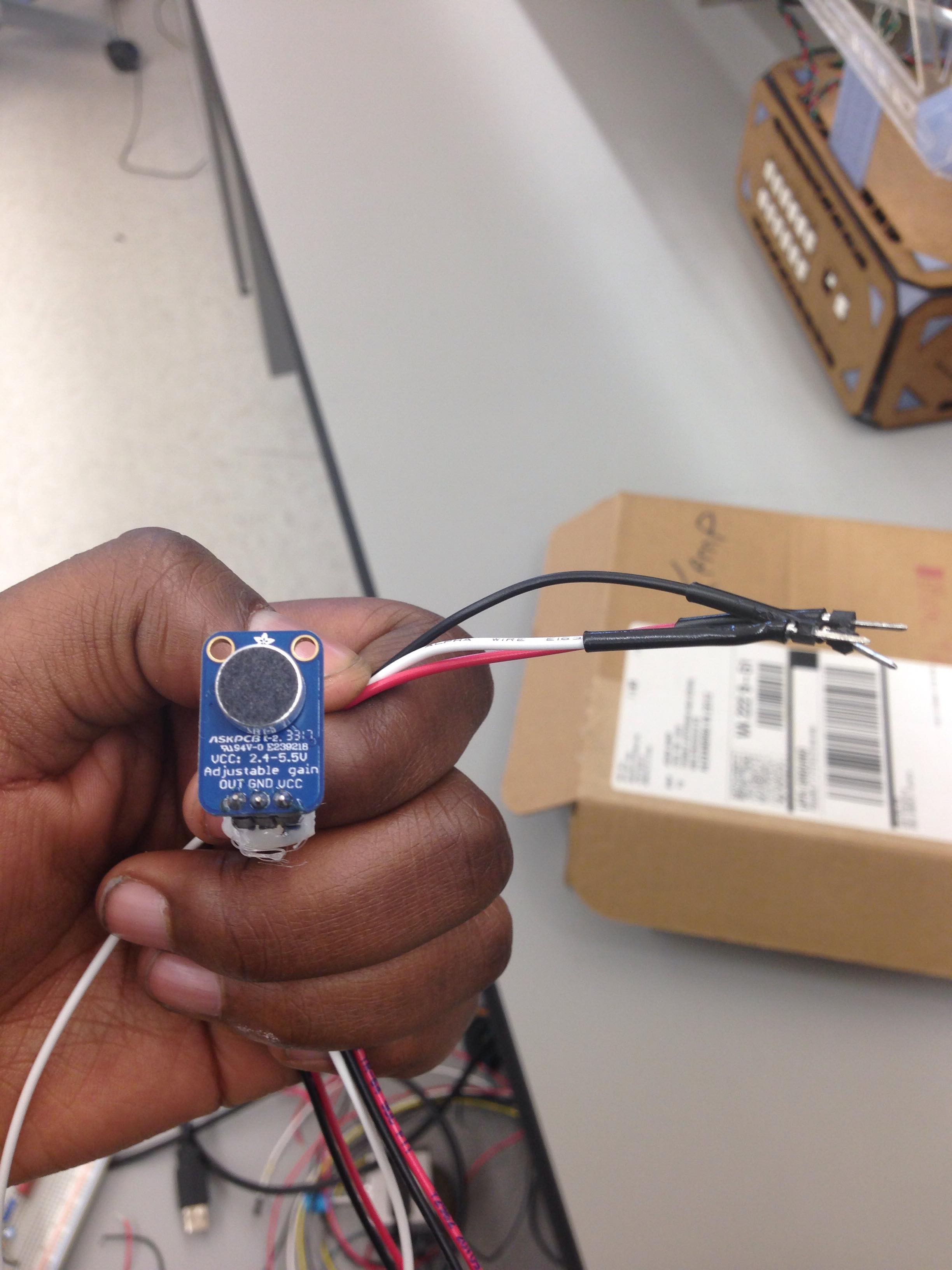

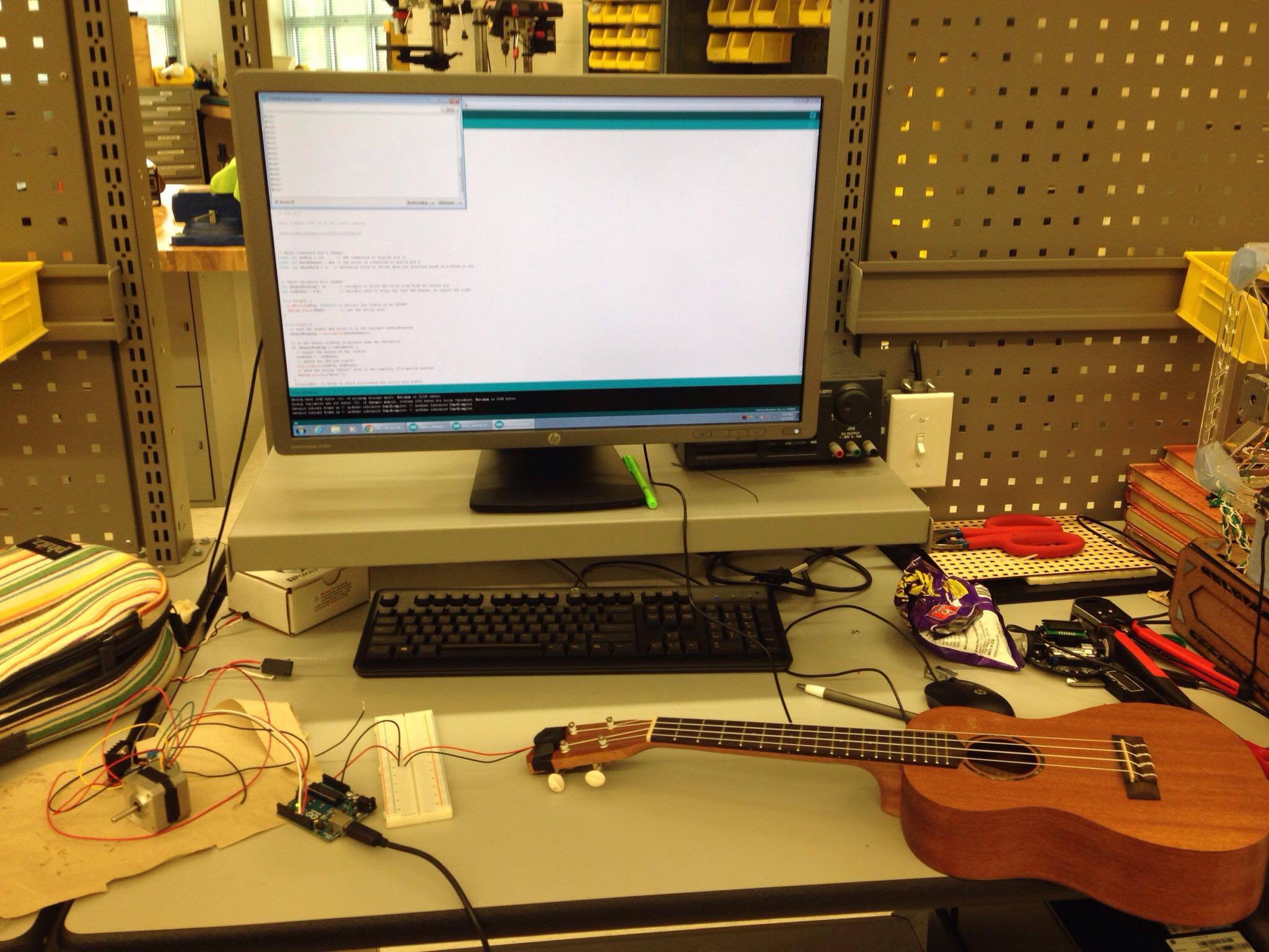
 Now that I have a sensor that gives good output (still debating on buying another version that's simpler and easier to use), I am now working on the most difficult aspect of this project: the code. Specifically, the FFT (Fast Fourier Transform) code that does all the work of determining the frequency of incoming raw data from sound/vibration waves. It's much easier to run FFT on something like Python or MATLAB, since arduino is more limited than those languages. However, libraries for FFT on arduino exist, and I'm currently trying to figure it all out or maybe write my own. It's very complicated, but I'm sure I'll figure it out.
 Jon VB
 Nigel
Nigel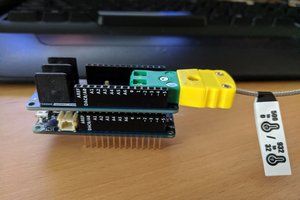
 eric
eric
 Ana
Ana