Close
0%
0%

6S IOT BMS

A BMS that publishes Cell Voltage to a MQTT Broker

Similar projects worth following
Energy storage for a 12V (boosted to 24V) solar system which publishes the voltage of each cell to a MQTT Broker (plan on using Adafruit.io) ether by using a SIM800 or the ESP8266 depending on the availability of WIFI.

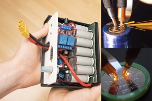
The BMS will be powered directly from the 6S pack using two 5V 1A Isolated PSUs.

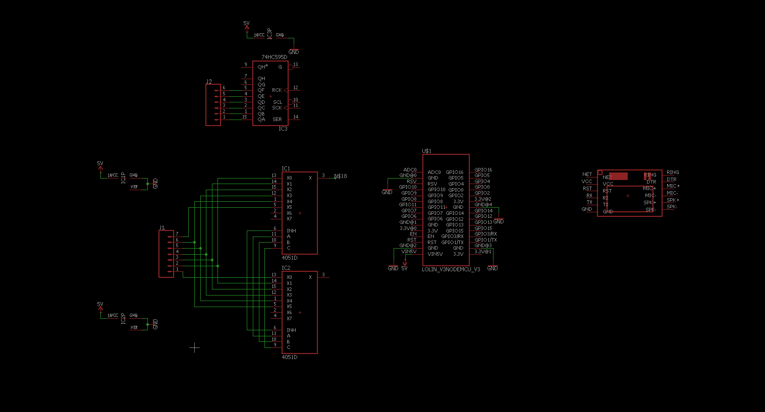
Two multiplexers will be used to access each individual cell for voltage measuring and if a cell exceeds the set voltage a external load will be switched on.

Every two minutes the cell voltages will also be published to a MQTT broker either via WiFi or the SIM800 module if there is only cellular service available.

  • 1 × ESP8266 NodeMCU
  • 1 × SIM800 Module
  • 1 × 74HC595 SOP-16 - Electronic Components / Misc. Electronic Components
  • 6 × 5W 10Ω Resistor Resistor
  • 6 × PC817 Opto and Fiber Optic Semiconductors and ICs / Optocouplers and Optoisolators

View all 12 components

  • Switching to the ESP32

    Johannes12/17/2017 at 09:47 0 comments

    I tried to work around the limitations of the ESP8266 but I soon realized that one Core isn't going to cut it. 

    My plans on how to use the ESP8266:

    • Battery Charging/Monitoring for 5 minutes 

    • Switching OFF the charging circuit and the balance resistors

    • Establish an connection to the Broker over WiFi or Cellular Service 

    • Publish the six cell voltages

    • Disconnect from the Broker

    • Switching ON the charging circuit and the balance resistors (if needed) 

    This process would leave the cells "unatened" during the publishing which I don't really feel comfortable with so I decided to change the MCU to an ESP32. 

    The charging circuit will still be switchable in case of an emergency (Overcharged cell) 

    Using the ESP32 the structure will look something like this:

    • Constantly charging/monitoring the Cells (Core 1)

    • Waking Core 0 up every 5 minutes

    • Establishing a connection with the broker using Core 0 (Core 1 still running and monitoring the cells) 

    • Core 0 publishes the cell values

    • Core 0 disconnects from the Broker (You know what Core 1 is doing here)

    • Core 0 shuts down to save energy

    During the whole connecting/publishing/disconnecting of Core 0, Core 1 independently monitors the cells so there isn't a single time where they are unattended. 

    I'll use the ESP32-Wroom Module, at this point I'm not sure if I'm going to use the BLE capabilities... 

  • Battery Modules​

    Johannes10/25/2017 at 16:58 0 comments

    I started designing battery modules which can hold 4x 18650s.

    It's just a quick prototype and will be refined in the future, probably making it modular so you can add as many 18650 cells as you like...

    They are keyed so there is no possibility to plug them in the wrong way.

  • In the beginning...

    Johannes10/15/2017 at 13:26 0 comments

    I thought about a few different combinations of MCU/Modules in the beginning (Arduino Pro Mini + ESP8266 + SIM800 or ATtiny85 + ESP8266 + SIM800) but I settled on only using the ESP8266 and SIM800.

    I wanted to use the Pro Mini/ATtiny because they have 5V ADCs whereas the ESP only allows a maximum of 1V at its ADC-Pin. The Pro Mini would also have been the brains of the whole BMS not like the ATtiny that would only have been used for measuring the different cell voltages and sending them to the ESP.

    While I'm waiting on the parts to arrive I started the schematic in EAGLE (nowhere near finished, spent most of the time searching for librarys). 

    I found a great library for the SIM800 module I ordered

    Couldn't find anything for the LoLin v3 so I created my own...

    I hope the circuit will fit on a single-sided PCB as I want to etch it myself.

View all 3 project logs

Enjoy this project?

Share

Discussions

Tom wrote 02/28/2018 at 08:23 point

With respect, 12 bits on the ADC is resolution.  Not accuracy.

https://www.esp32.com/viewtopic.php?t=1045

  Are you sure? yes | no

Johannes wrote 02/28/2018 at 19:27 point

Sorry, I got you mistaken. I thought you were revering to the accuracy by the "Voltage Steps" the ESP can measure.

Thanks for the Link though. It seems like I should implement some calibration procedure and use the ADC without the Attenuation-feature.

  Are you sure? yes | no

Tom wrote 02/27/2018 at 08:27 point

Are the ADCs on the ESP32 reliable enough to calculate accurate cell voltages?

  Are you sure? yes | no

Johannes wrote 02/27/2018 at 21:55 point

The ESP32 has 12bit ADCs so the should be quite accurate. I can't say anything on their reliability/repeatability as this is my first time working with the ESP32 but even if it fluctuates a few mVolts it wouldn't that big of a deal...

  Are you sure? yes | no

Similar Projects

Does this project spark your interest?

Become a member to follow this project and never miss any updates