 Carlos Garcia Saura
Disclaimer
This is an experimental design, at the moment IT MUST NOT BE USED IN CRITICAL APPLICATIONS. The author(s) of this project are not liable for any damage or responsibility derived from the use or misuse of the Open Radiation Detector.
Challenges addressed
The project started as a personal challenge to build a true low cost radiation detector. For this we needed to tackle the following problems:
- Decide the detection method among all the options (see log entry 1).
- Design prototypes and test them to assess performance (see log entry 4).
- There were problems with electrostatic affecting the measurements. See how we solved it in entry 6.
- Thorough the whole project, optimize the design for pick-and-place manufacture with the least components possible.
List of specifications and how they will be met
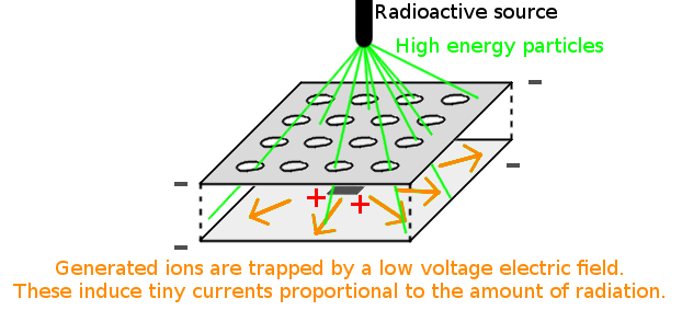
- It must tell if an object is substantially radioactive. There is a lack of low cost options to measure alpha radiation (see log entry 1: introduction to radiation detectors). We decided to go for a ionization chamber design for the following reasons: as opposed to other detectors, ion chambers are simple and don't require high voltages, any vacuum tubes nor delicate mica windows. Still, they are really good at detecting alpha radiation (see log entry 2: DIY ion chambers).
- The Open Radiation Detector must be small and low cost. We have already gone through many prototypes and iterations: a spark detector, and many different shapes of ionization chambers (see the log entries).
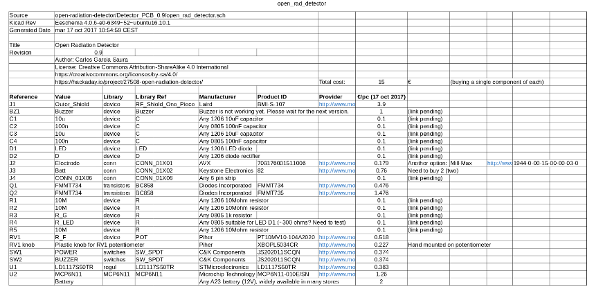
- It must use standard, modern components. Existing DIY designs that can be found online are great, but they rely upon old transistor models that are difficult to find. For this project we have studied more up-to-date options (see log entry 5).
- Preference goes to facilitating pick-and-place assembly. Existing DIY projects use recycled tin cans and hand-made parts. We have designed an ion chamber that is built with low cost SMD components and can be assembled with pick-and-place machines. These components originally had completely different purposes, but we arranged them to work as an effective ion chamber (see log entry 4).
- It must be open source. We don't believe in patents, specially in the field of safety. The on-line maker community is the best place to share this design and ensure that it reaches the places and applications that may benefit from the Open Radiation Detector.
Will it be world changing?
The goal of this project is to facilitate the identification of radioactive hazards by creating a low cost & mass-producible detector.
Like it or not, the world has become more and more radioactive since the discovery of nuclear energy. Containing radioactive waste is a real problem, and some nuclear disasters have shown us that we live closer to radiation than we think.
The Open Radiation Detector can tell if an object emits dangerous levels of radiation (these are often imperceptible - radiation doesn't glow like in movies!). Our hope is to be sensitive enough to tell if food is contaminated, though we don't know how to test this sensitivity yet. The detector could also be placed in low-cost swarms of disposable robots that roam around a disaster area and mark the hot spots that should be avoided by humans.
We have shared a novel design that uses standard components and can be assembled by pick-and-place machines. There are similar DIY radiation detectors out there, but none of them can be mass-manufactured consistently at such a low cost.
How it works
The detector uses an open-air ion chamber polarized with a transistor amplifier circuit that notifies if high radiation levels are present.
- Introduction to radiation detectors
- The background: lots of DIY projects
- First attempts: an alpha spark detector
- Ionization chamber prototypes
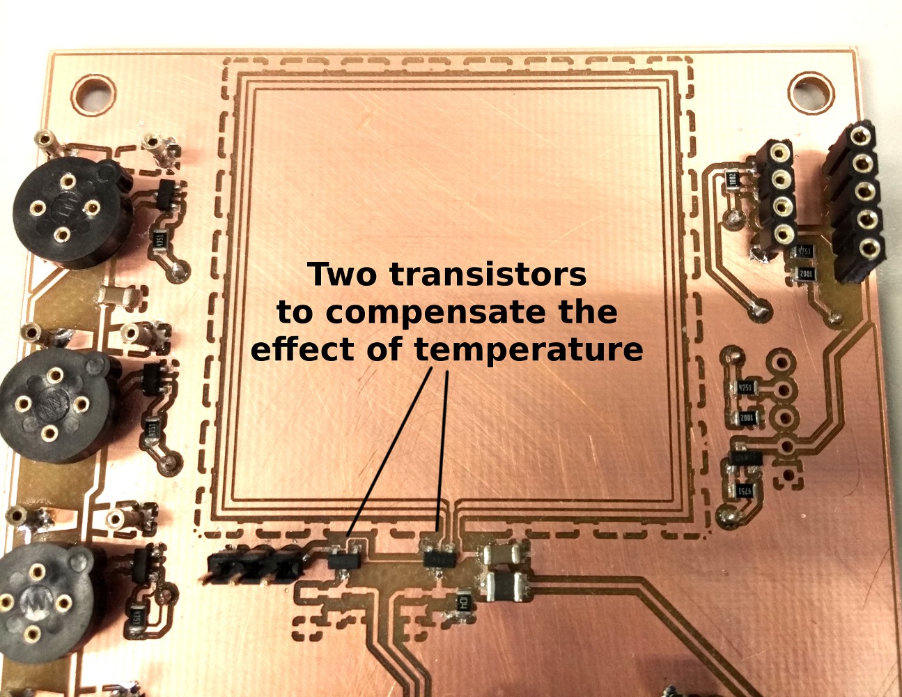
- Correcting the effect of temperature
- Reducing the effect of static electricity
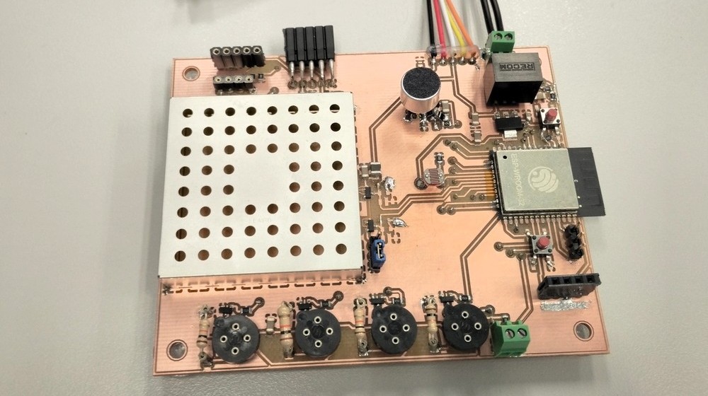
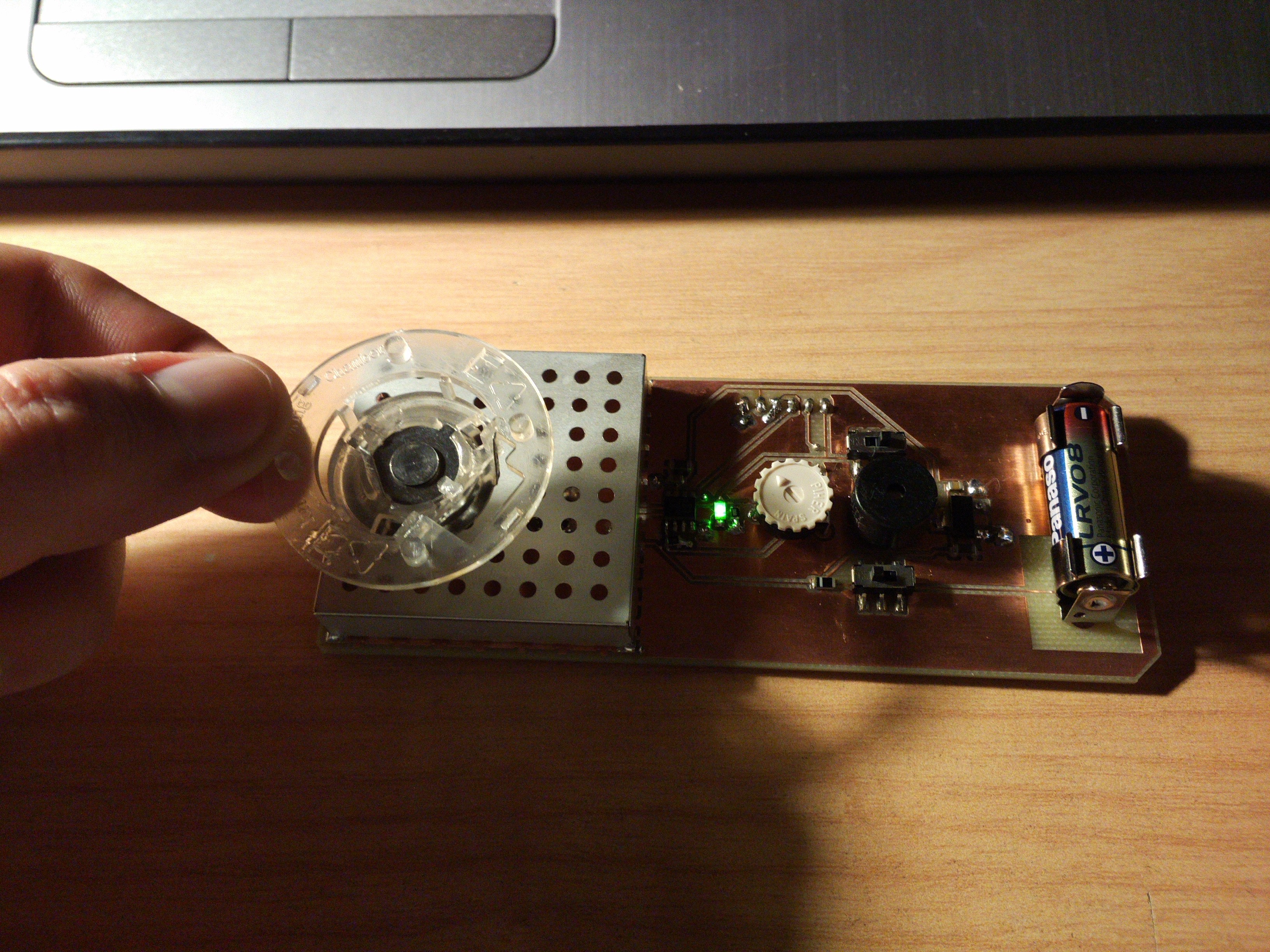
- The hand-held detector
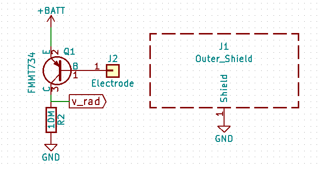
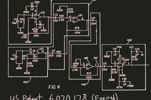
- Schematic for the amplifier circuit
- PCB electrode...
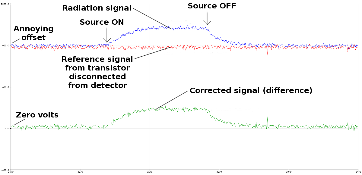
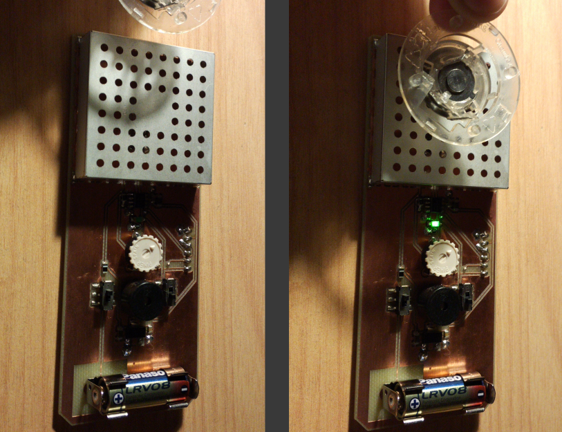 We were most excited to see that electrostatic fields now do NOT affect the measurement! So all the modifications since last version have been for the good :-)
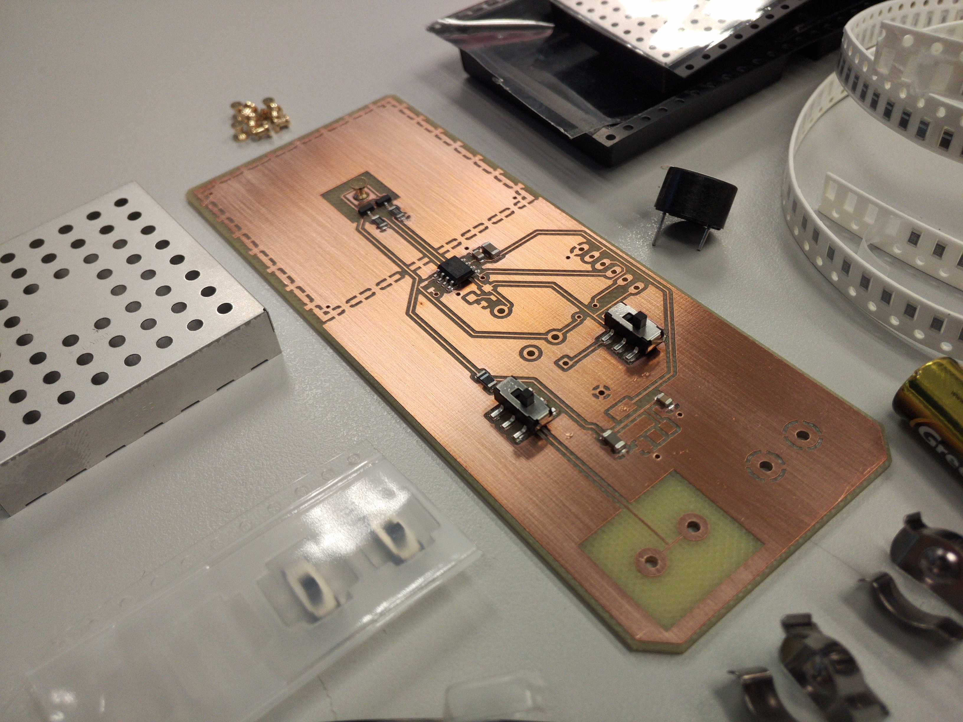
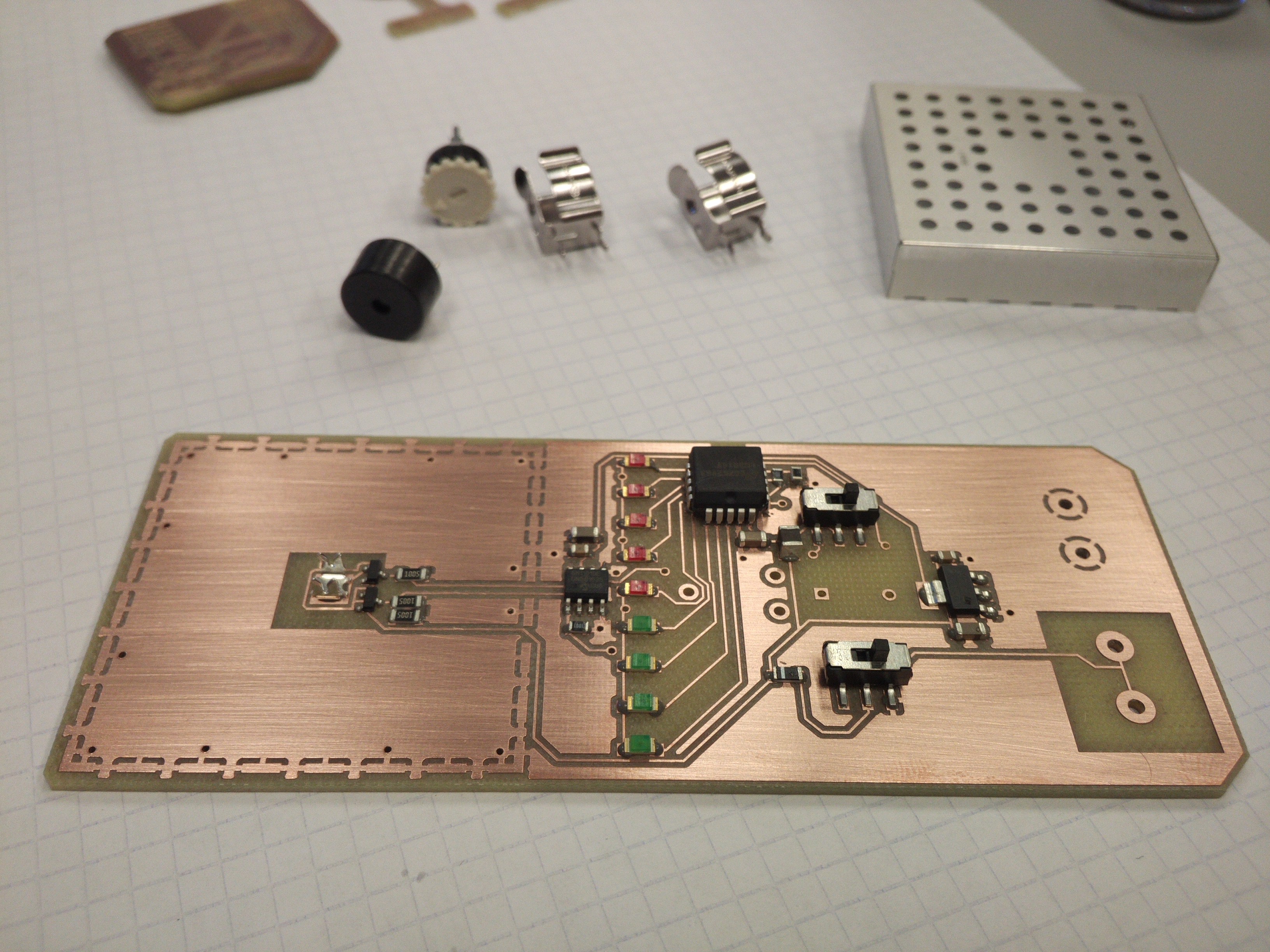
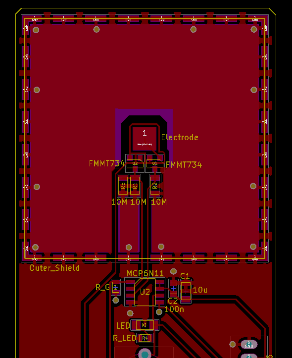 The central electrode is a surface-mount stud that captures the tiny ionization currents within the chamber. It is tightly coupled with the Darlington transistor that amplifies the signal (see
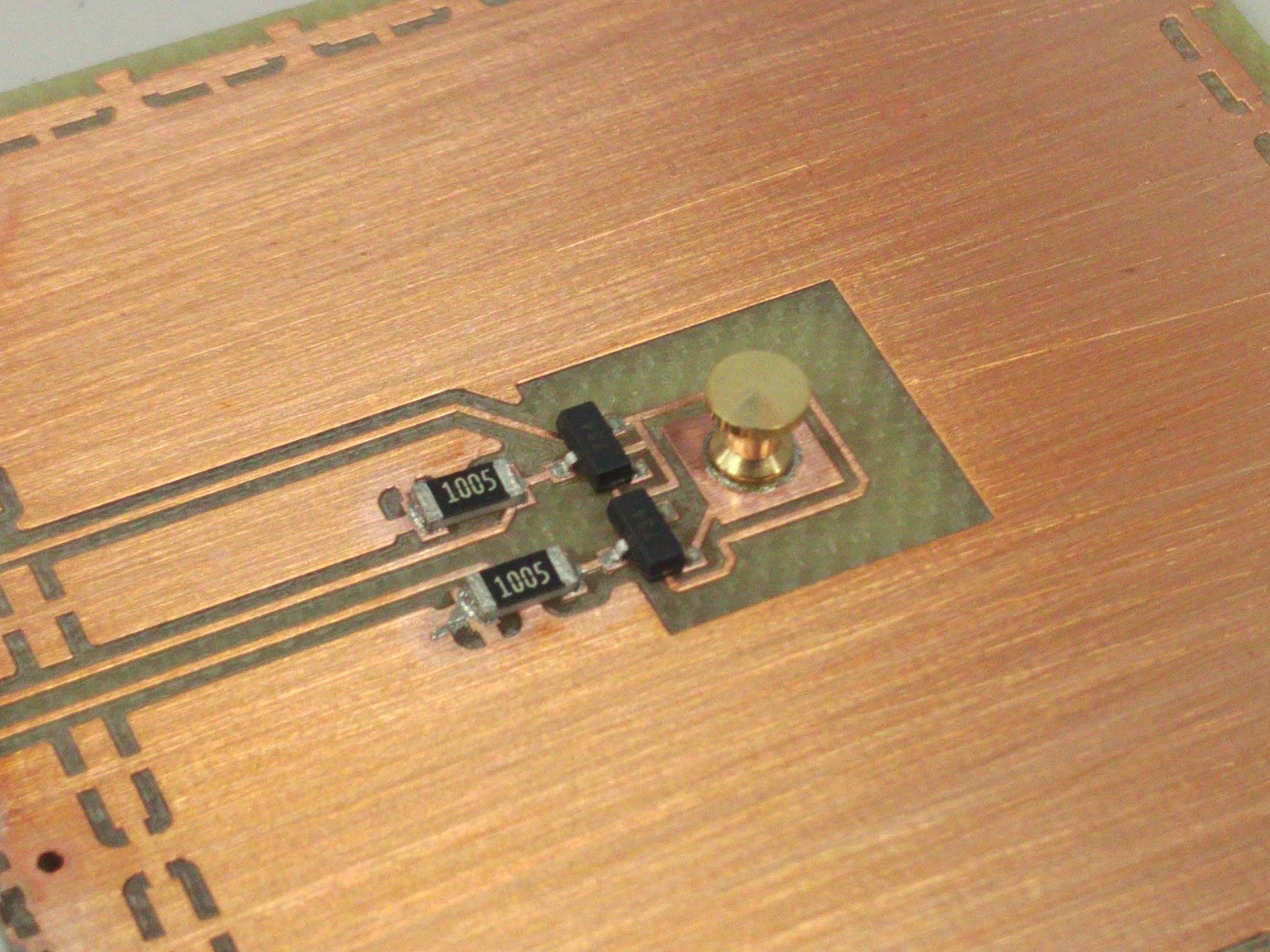
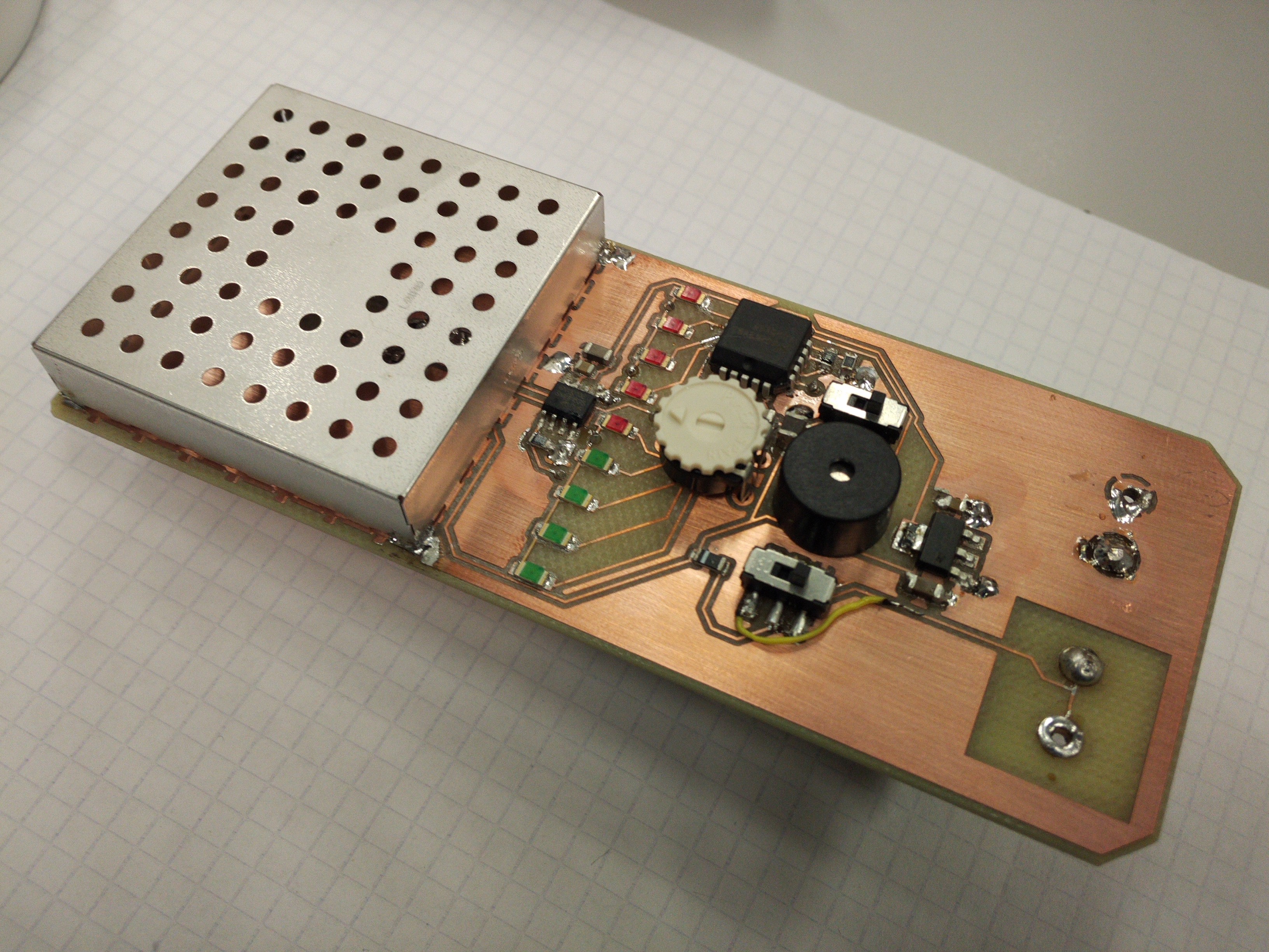
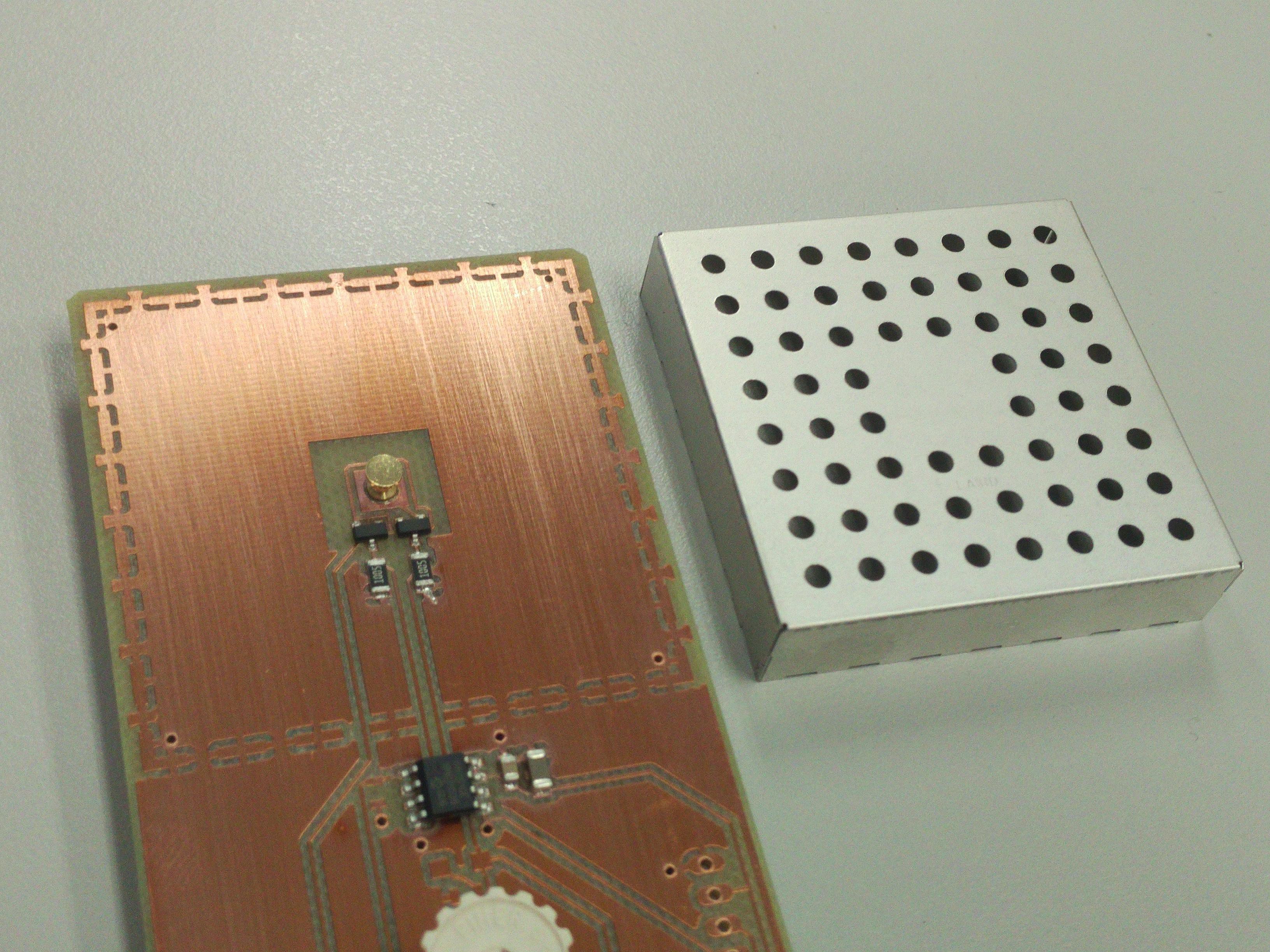 On the bottom can be seen the instrumentation amplifier that conditions and further amplifies the signal while compensating for the temperature effects (see entries
 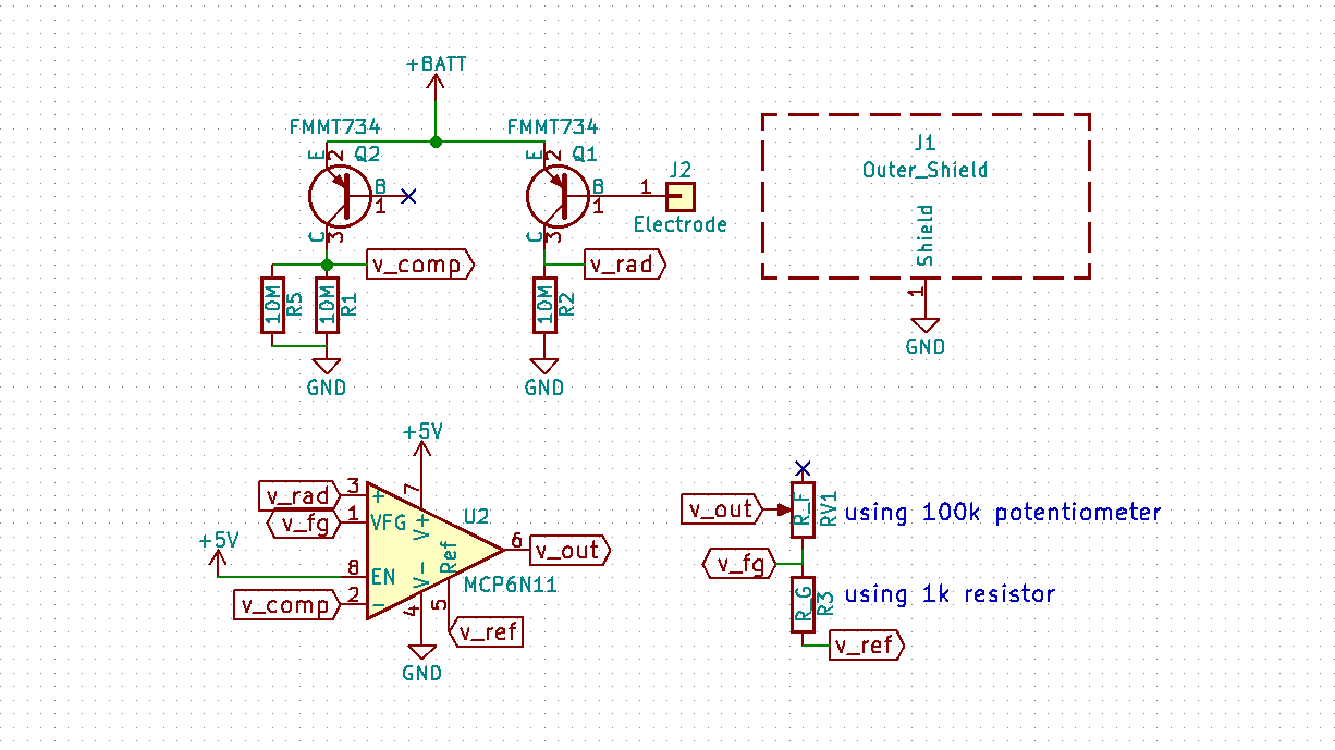 Amplification is achieved with a pair of
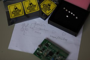
 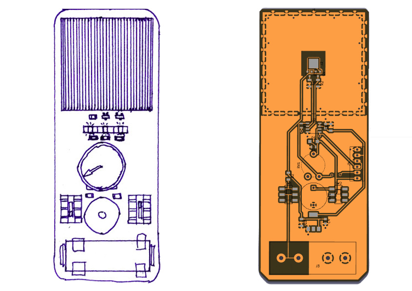 The sketch on the left was made at the start of the project. Next to it you can see the latest design :-)
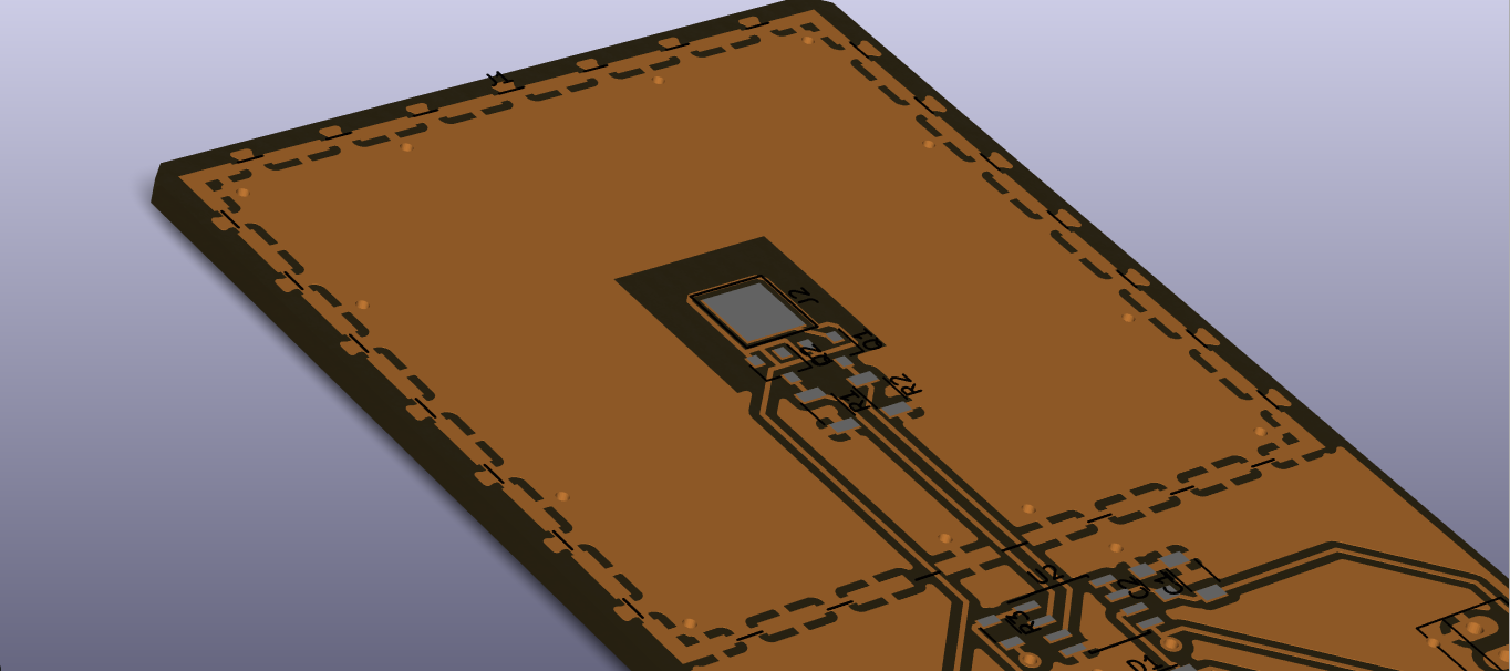 Next entries will show more details on the schematic.
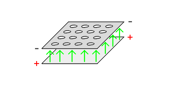 As can be seen, in electrical terms the circuit is a capacitor.
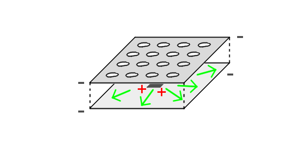


 Tom Anderson
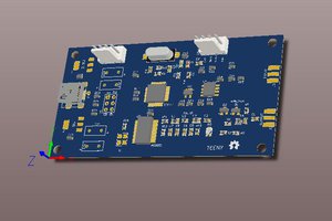
 glenpyeldho
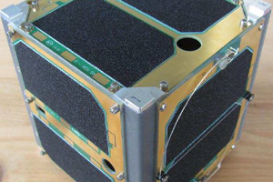
 sparks.ron
Hi Interesting project :) do you have instruction on how to build the metal box ? " the chamber"