As I know very little about video signals, to me the video output of the PCW was some complicated mystery. I knew the sync signal would indicate, somehow the end of the line and the end of the screen, and the other signal would have the picture data, but I wasn't sure what format it was in, and thought it would be too fast for my logic analyser to capture it.
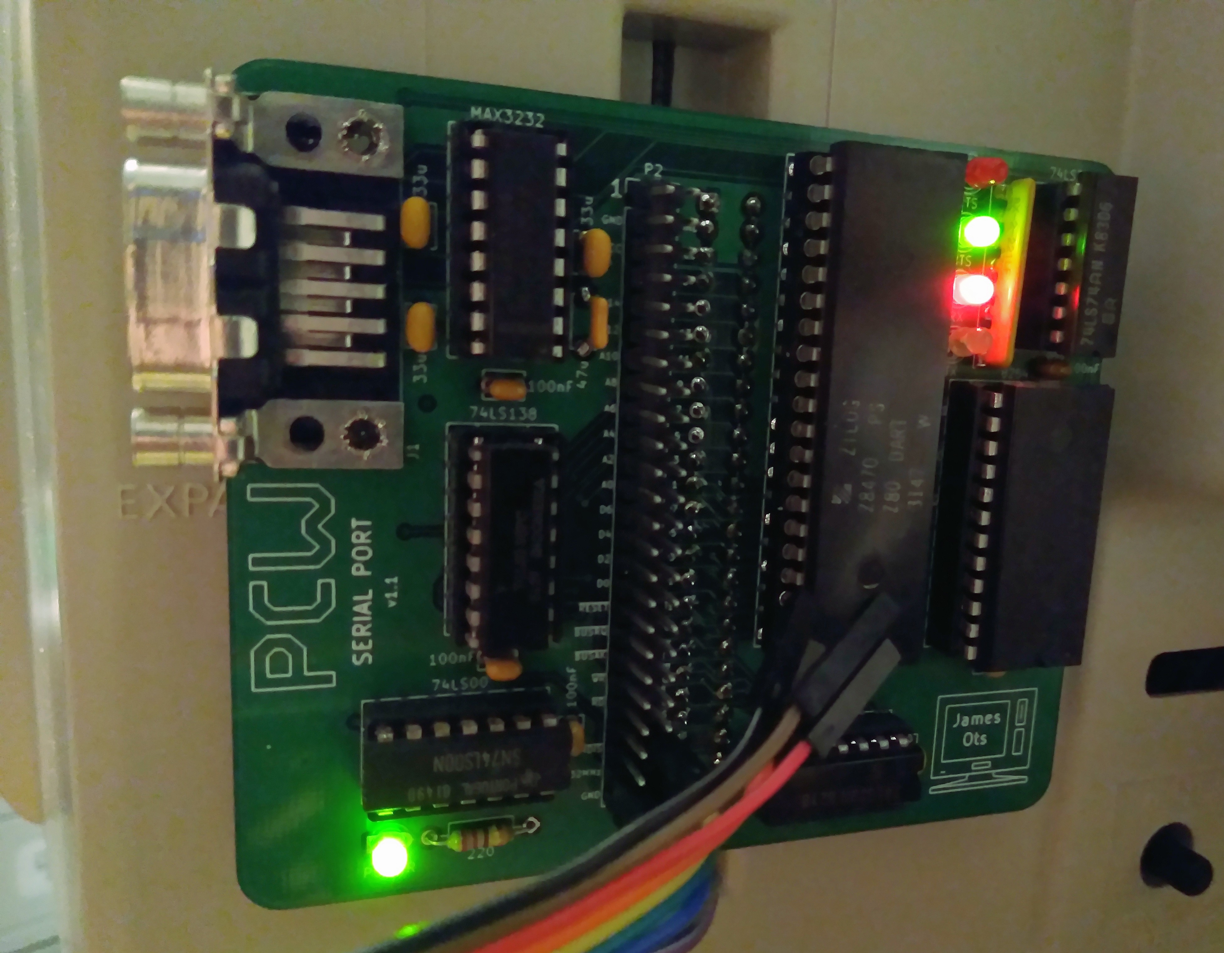
Then yesterday I thought about it and realised that the signal should actually be slow enough, as my logic analyser can capture up to 24MHz signals in theory. So I connected it up, using the serial port I made a while ago — I had put pin headers on the back of the board, 'just in case', and they finally came in useful.

I switched on the PCW and captured 10 million samples of data, and discovered I actually had meaningful data. NSYNC is usually high, and it goes low for 4µs at the end of every line, which is 64µs long (including the low pulse). The VIDEO signal simply toggles between low and high, for dark and bright pixels. Each pixel is 0.0625µs long, making an 8-pixel character 0.5µs long, and a whole line 45µs. (Although there is of course some extra time/space at the start and end of each line).
This is a capture of the start of the first line on the screen:

(The 32MHz clock showed up as 8MHz, since it's faster than the sample rate). You can tell it's the first line of the screen, because if you examine it, it matches the pixels that were displayed:

I put the captures of the first 8 lines together, and got this:

Which shows that there was some aliasing, as the 25MHz of the logic analyser is a bit too close to the actual signal frequency.
This is a capture showing the end of the screen (where it says Drive is A:). At the end of every screen there's a series of four vertical sync pulses, each of which is 60µs low and 4µs high (the opposite of the signal for every other line).

There are 16 blank scanlines at the end of the screen and 44 at the start. The displayable area of the screen is 32 × 8 lines (256), which makes 316 altogether, plus the 4 vertical sync pulses, which makes a total of 320 × 64µs, which is 20480µs. Multiplied by 50Hz gives 1.024 seconds per screen. Which probably means the timings I have are all a tiny fraction of a microsecond faster than the logic analyser says they are, or that the screen isn't quite running at 50Hz. It's good enough for me at the moment, but I'll probably go and read up about video signal timing now.
 James Ots
Discussions
Become a Hackaday.io Member
Create an account to leave a comment. Already have an account? Log In.
I did some further timing, and 50 frames actually take around 1000.55µs, rather than 1024µs, which means I'm about 0.469µs out per frame. Since I've found various things which say that one scanline should be 64µs, I'm guessing the vertical sync pulses are very slightly shorter than that?
Are you sure? yes | no