deʃhipu
-
Daring a Ludum
12/02/2017 at 16:46 • 0 commentsI'm taking part in Ludum Dare this weekend. You can see my progress here: https://ldjam.com/users/deshipu/feed
So far so good:
-
Battery Life
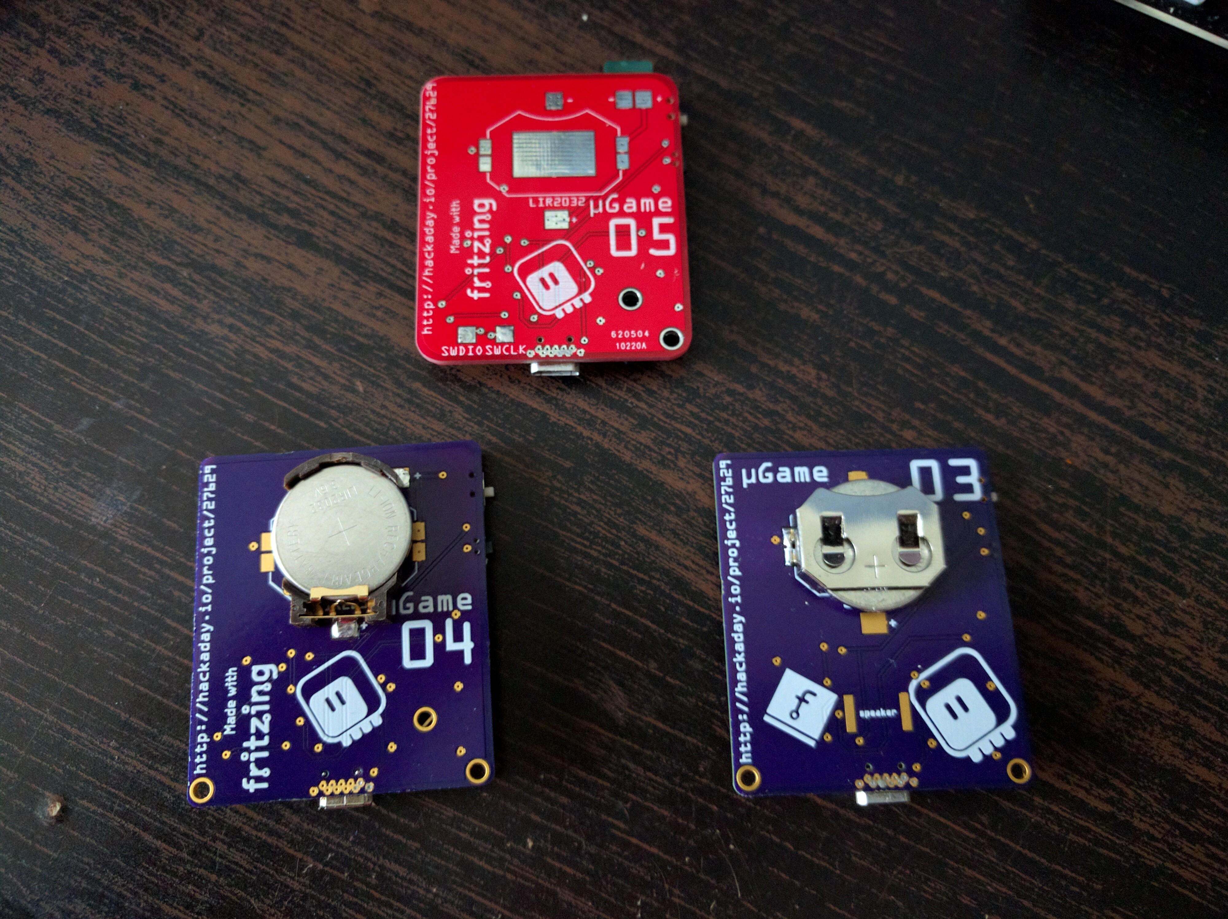
12/01/2017 at 23:40 • 0 commentsSince I entered this into the #Coin Cell Challenge, I'd better write something about the battery power. All the prototypes so far have on their back a socket for a LIR2302 battery, and a built-in charging circuit. The later prototypes also have connectors for other batteries.
![]()
The 40mAh LIR2302 lets you play for about... 40 minutes. I didn't add any sound to any of my games yet (thought I did test that it works well with wav files) — I expect that using sounds will shorten the play time somewhat.
The charging circuit has been limited to around 40mA, so that it won't damage the tiny batteries.
It is possible to use a different LiPo battery than the coin cells. For example, a battery from a small cellphone (not smartphone) works well, especially since it's about the same size as the device and nicely fits flat on the back. In such case it's recommended to replace the current-setting resistor in the battery charging circuit to a 10kΩ (for 100mAh battery) or even 5kΩ (for 200mAh battery or larger), for faster charging.
-
Version 5
11/29/2017 at 23:59 • 1 commentThe PCBs for version 5 arrived. It took some more time, because I ordered them from China — this time I wanted 10 red PCBs, to make a bunch of prototypes that I can give to interested people for testing.
![]()
Here I also experimented with using half of an SD card box as the case for the back, held together with some tape. Maybe not pretty, but functional. I might actually go with those boxes, if I figure some way to attach them better.
There is one annoying problem with this version. While the screen display I used in the first prototypes (and re-soldered to every new prototype) worked without issues, the new displays I got refused to get initialized for some reason. I tried lowering the SPI clock, adding all kinds of delays, etc. — all for nothing. Then I soldered some wires to the MCU pins and connected a logic analyzer to see what the problem is, and suddenly the screen worked! There must be some noise on the pins when the SPI peripheral resets, and since the CS pin is hardwired down, that de-synchronizes the communication. The weak pull-downs of the logic analyzer are enough to avoid that noise. As a fix, I added a 200kΩ pull-down resistor to the clock pin — fortunately it's on the corner of the MCU — and that seems to make the display work reliably.
Another problem with this and previous versions is the audio circuitry. I didn't really have much space for it, so it's all tucked next to the fire buttons. The problem with this is that it's really easy to touch the amplifier's input pin with your finger, which results in unpleasant noise.
A third problem is that the charging LED switches on whenever you connect USB power, no matter if the battery is connected or not. Ideally it would only come on when the battery is charging.
So of course I had to make version 6, which has all those problems (hopefully) fixed:
- I swapped places of the battery charging circuit and the audio circuit. Now the amplifier and speaker are on that narrow strip next to the screen, where they are safe from fingers, and the charging circuit, together with the led, is in the lower right corner. As a bonus, there is a mounting hole there too now.
- I disconnected the CS pin from GND and connected it to one of the MCU pins. This way I can synchronize the communication by releasing the CS pin once in a while.
- The charging LED is now powered from the battery. No battery — no light.
- There are some doodles on the back:
-
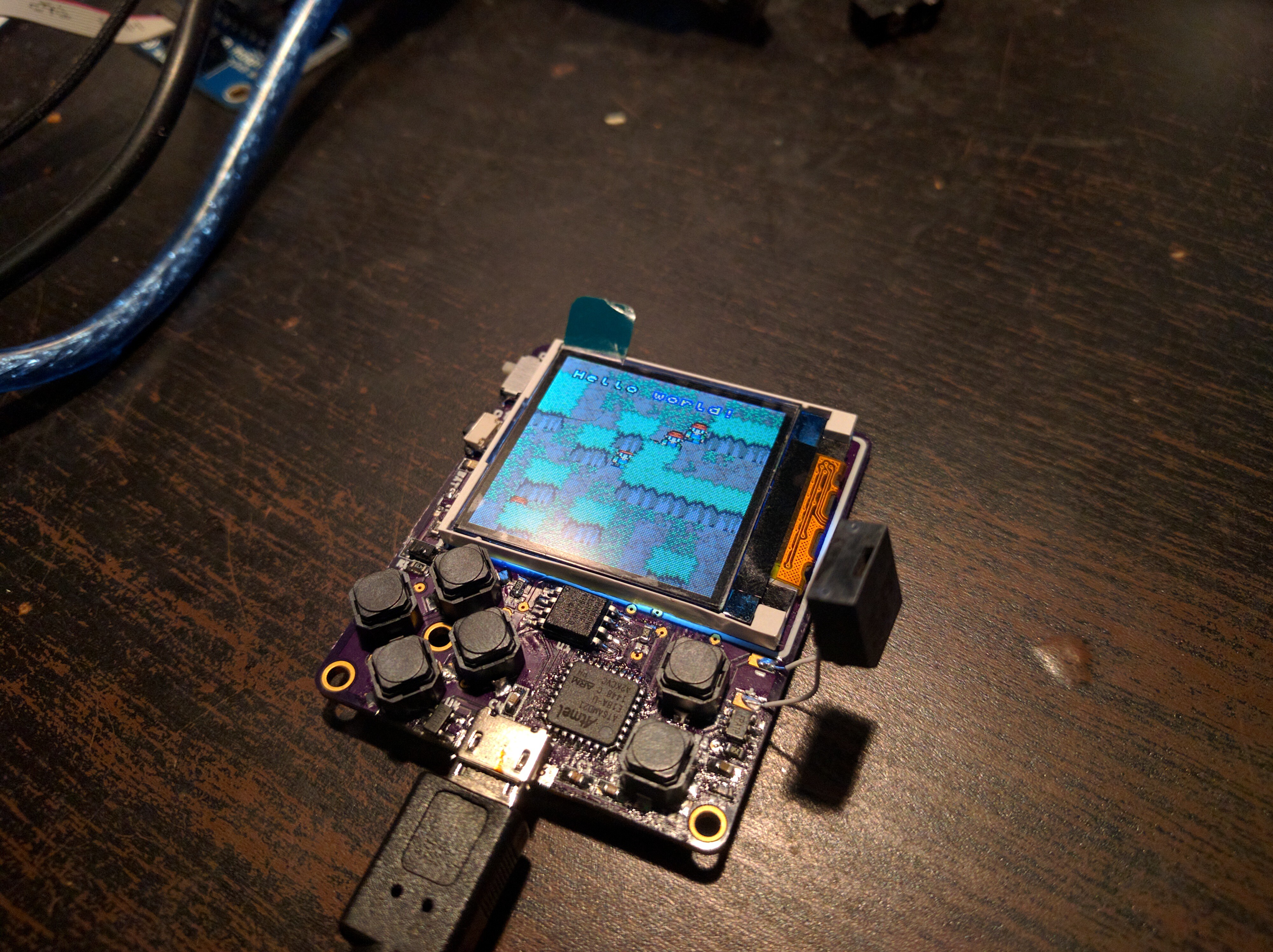
First Game
11/26/2017 at 19:56 • 0 commentsIn order to write a good game framework or library, you have to make games. There is no other way — you won't know whether you have all the necessary features until you actually try. And you won't know if a feature is actually necessary until you need it. So the best way is to make a game, then another game, and then yet another game, and once you have covered the spectrum of different kinds of games you want to be able to make, you take all the bits and pieces from them and collect them in a single consistent library.
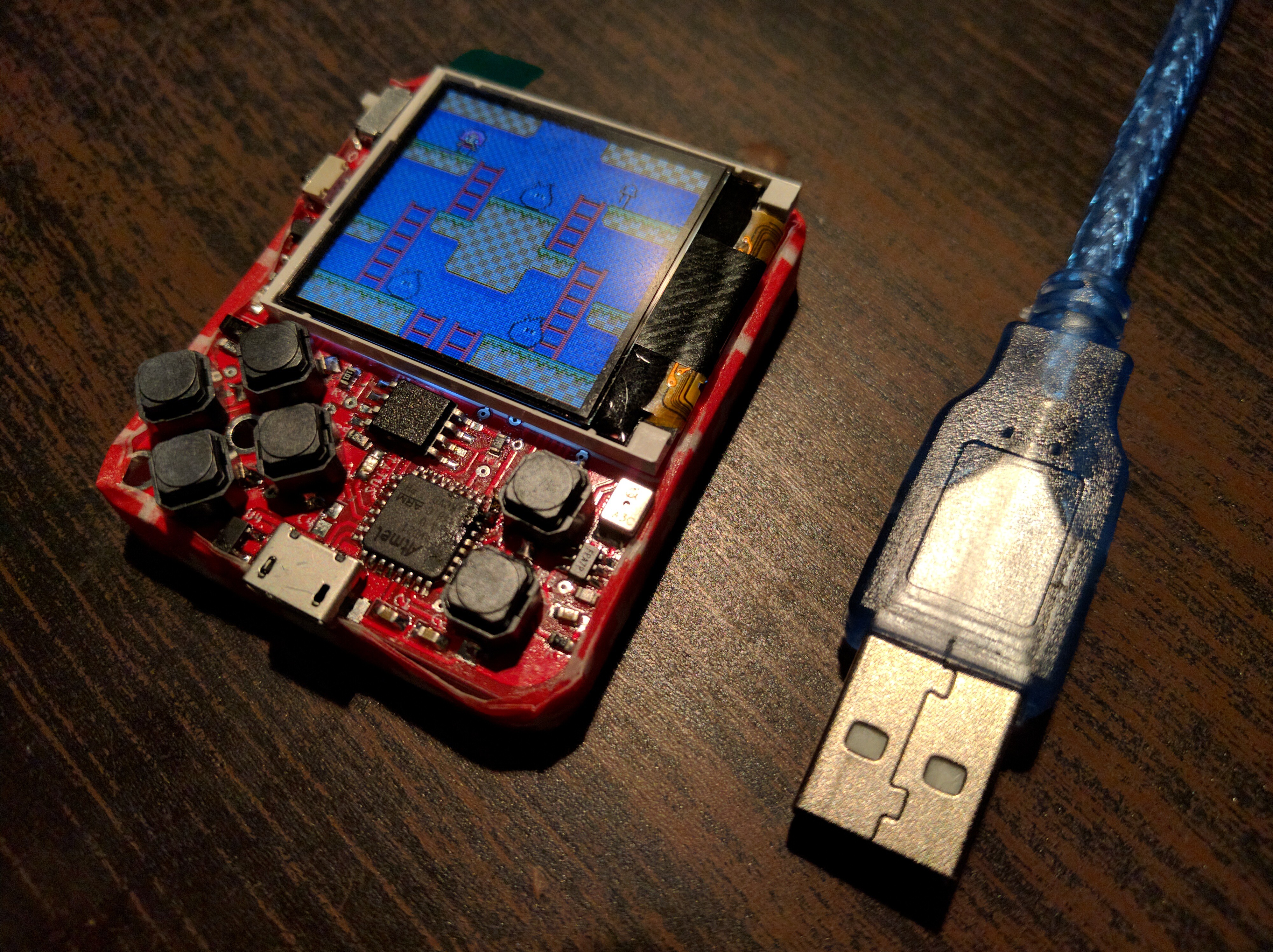
So far all I had for µGame was a simple "character walking around a map" demo. I needed to make an actual game. What I would most like to make are Japanese-style RPG games and roguelike games, but that would be a bit too much for a start, so I decided to make a platformer. And since there is no way to do scrolling, I decided to try and make a Bubble Bobble-style platformer, where you only see one screen at a time.
![]()
Of course it's not a fun and challenging game — that would require a lot of playtesting and fine-tuning. But it has all the elements that such a game needs to have: the hero, the monsters, walls, platforms, ladders, jumping, shooting, picking up loot, death. It loads all its resources from BMP files (two banks 16 tiles each), and that, together with a non-precompiled code, pretty much uses up all the RAM on the device. But fear not, you can compile the source to .mpy files, which should free up some more space, and you can always compile the graphics into the firmware, in which case it frees 4kB of RAM for you. You also can have much more levels, since only one level is loaded into RAM at once, and there is plenty of flash space free.
Next up will be some kind of a puzzle game, and then maybe a space shooter. I'm also still working on a set of default graphics to be pre-compiled into the firmware, to save you more precious RAM.
The repository with the game is at https://github.com/pewpew-game/circuitpython-jumperwire and you will need the firmware from https://github.com/pewpew-game/circuitpython/tree/ugame/atmel-samd/boards/ugame to run it.
-
Homebrew
11/25/2017 at 16:35 • 0 commentsThis device I'm building is not very beginner-friendly. It uses all SMD components, a bare displays screen, needs you to flash the bootloader to a bare chip and compile your own CircuitPython, etc. Quite a bit of work, to be honest. On the other hand, I would like the software library I'm making for this to be generally useful, and not just limited to this one device. So I wrote it in a way that lets you use it with pretty much any SPI display with 16-bit colors, and any buttons. Today I went and made a "homebrew" version of µGame, to show that it really doesn't have to be hard.
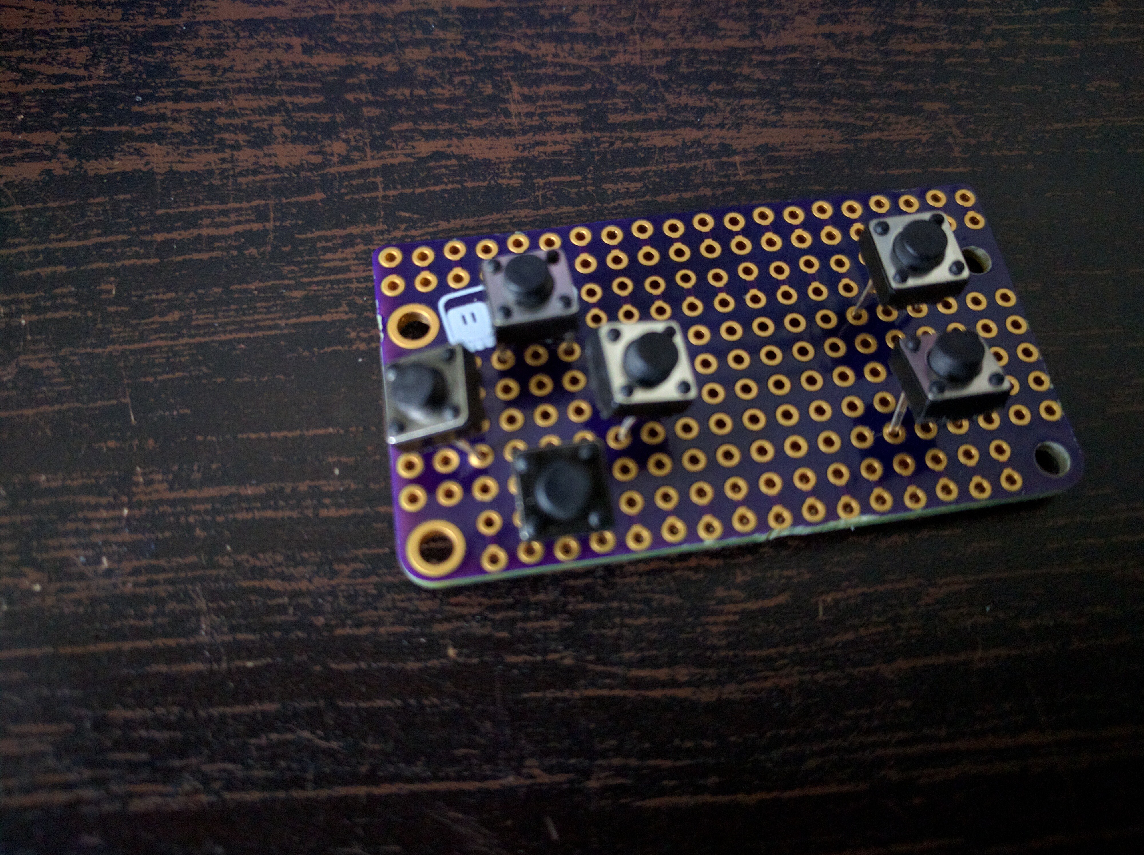
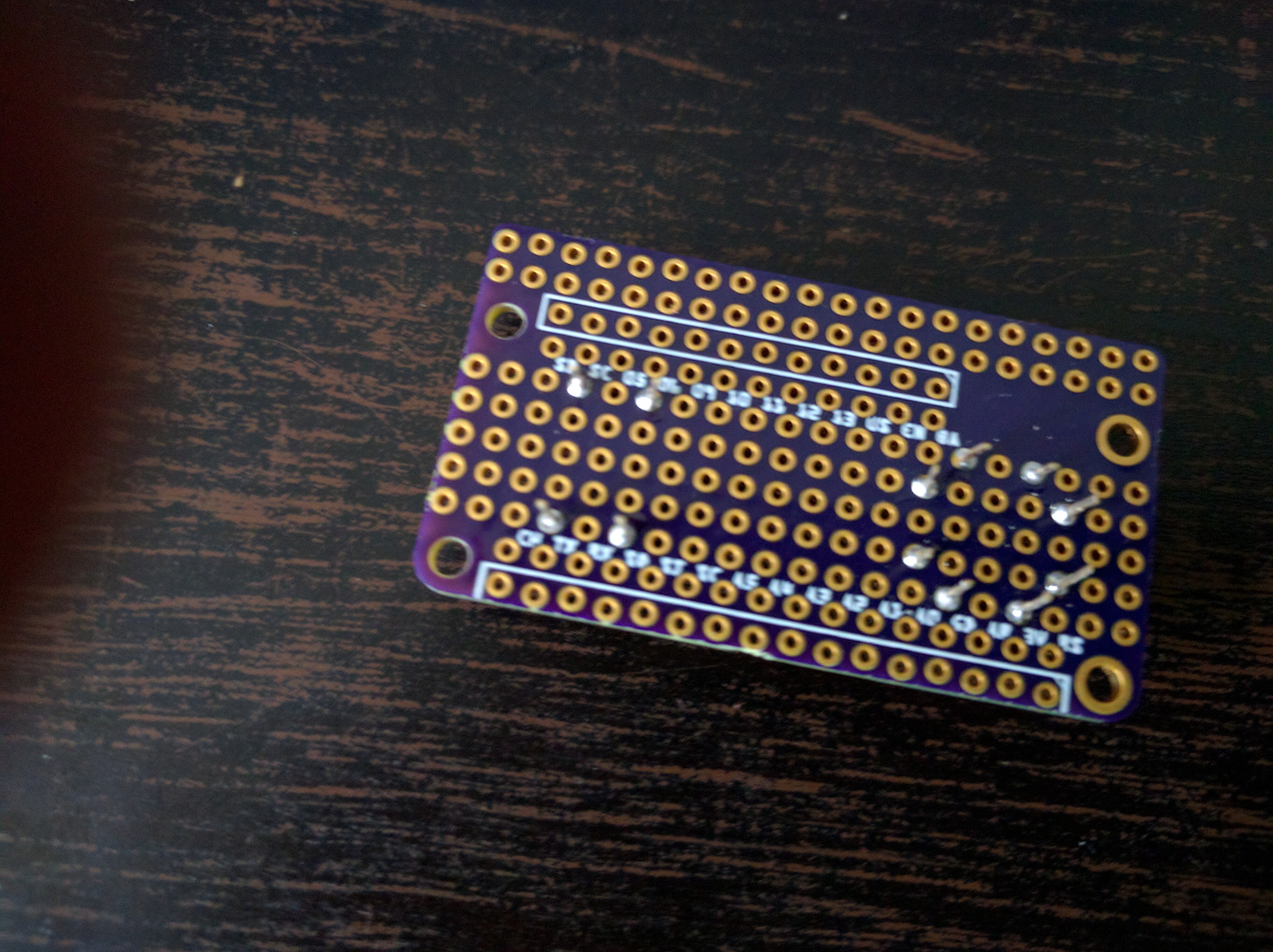
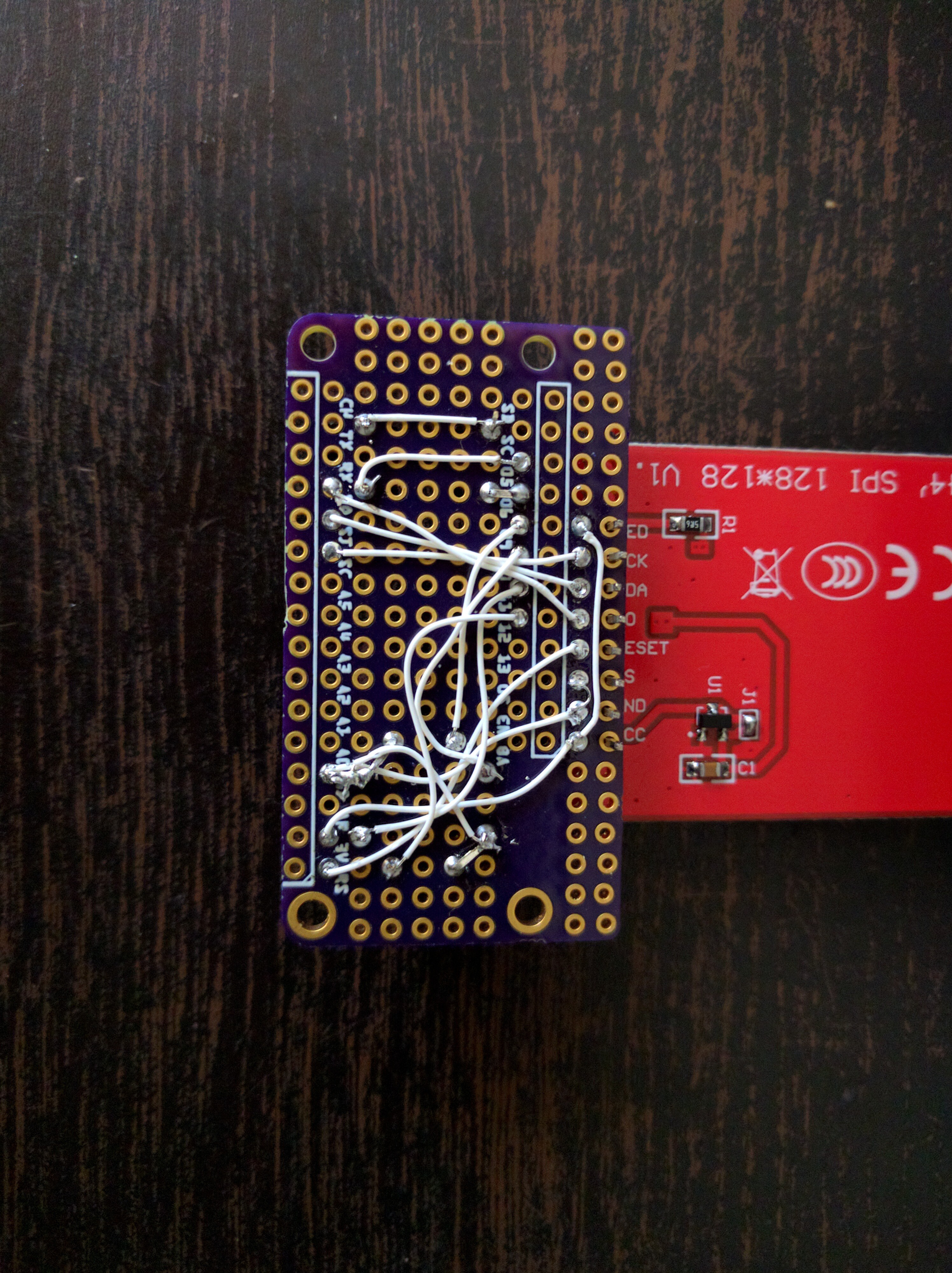
My initial experiments used a Trinket M0, but to really write an interesting game you will probably need much more room, so this time I used a Feather M0 Express, which has an additional flash chip. I also used a breakout board I made for displays, and a bunch of buttons:
![]() ---------- more ----------
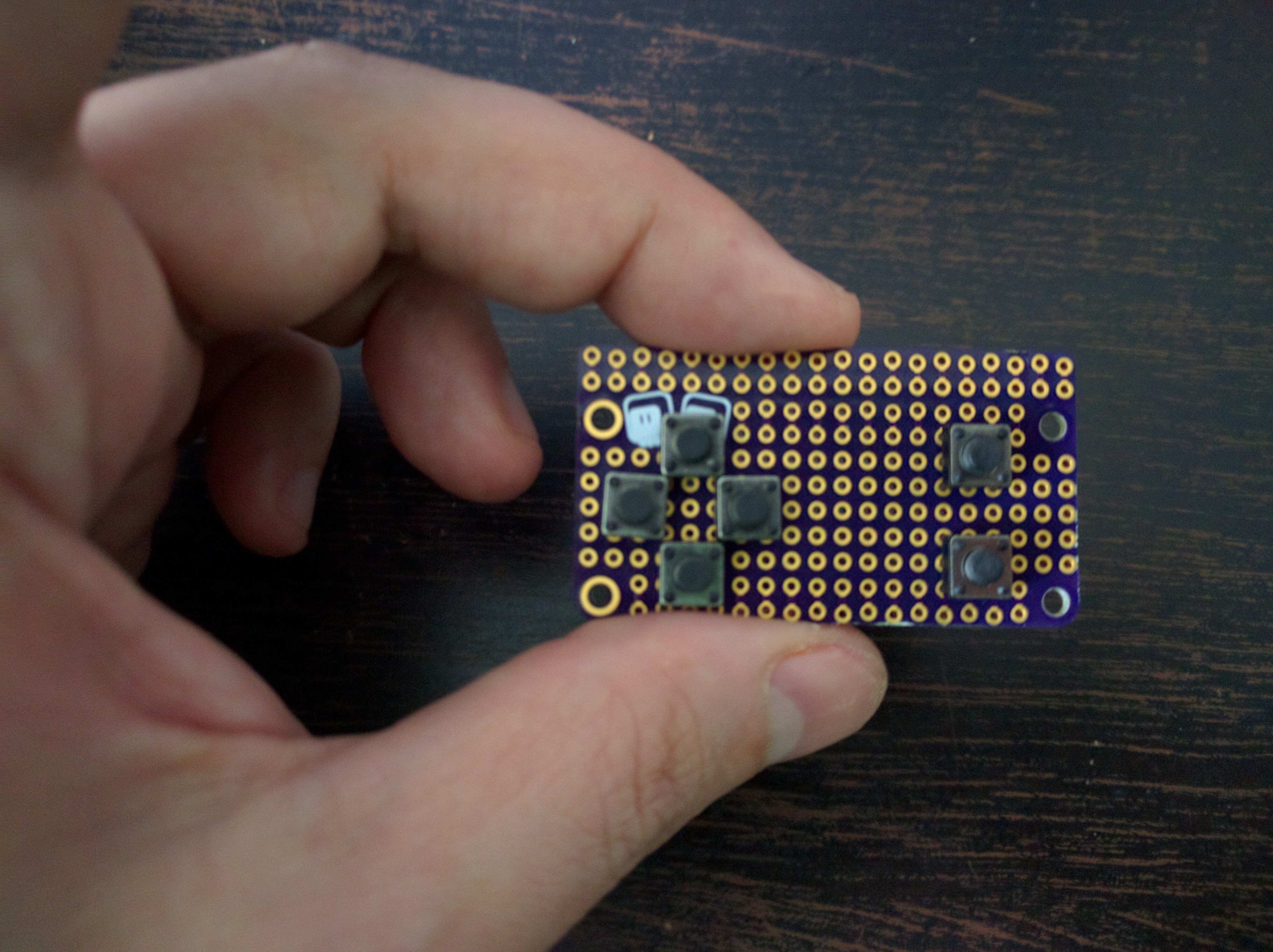
---------- more ----------I had to bend the legs of those buttons a little bit, to pack them on the board tightly enough:
![]()
A little bit of soldering:
![]()
And we have out gamepad:
![]()
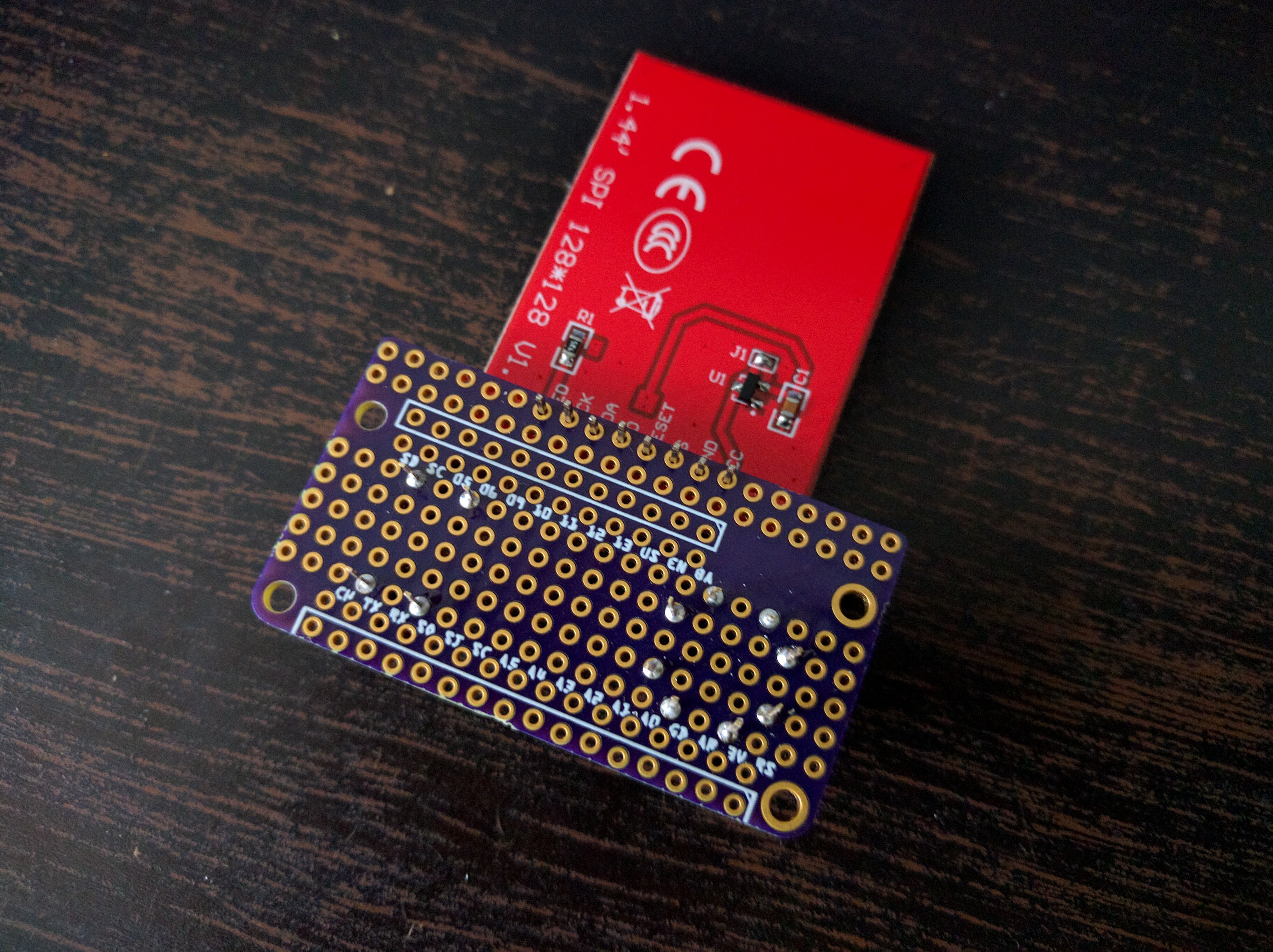
Next, we need to wire the display module. I used a module with the same ST7735R display as I used on the µGame, so that I can use the same code, but you can also use SSD1331, SSD1351, HX8353 or ILI9341.
![]()
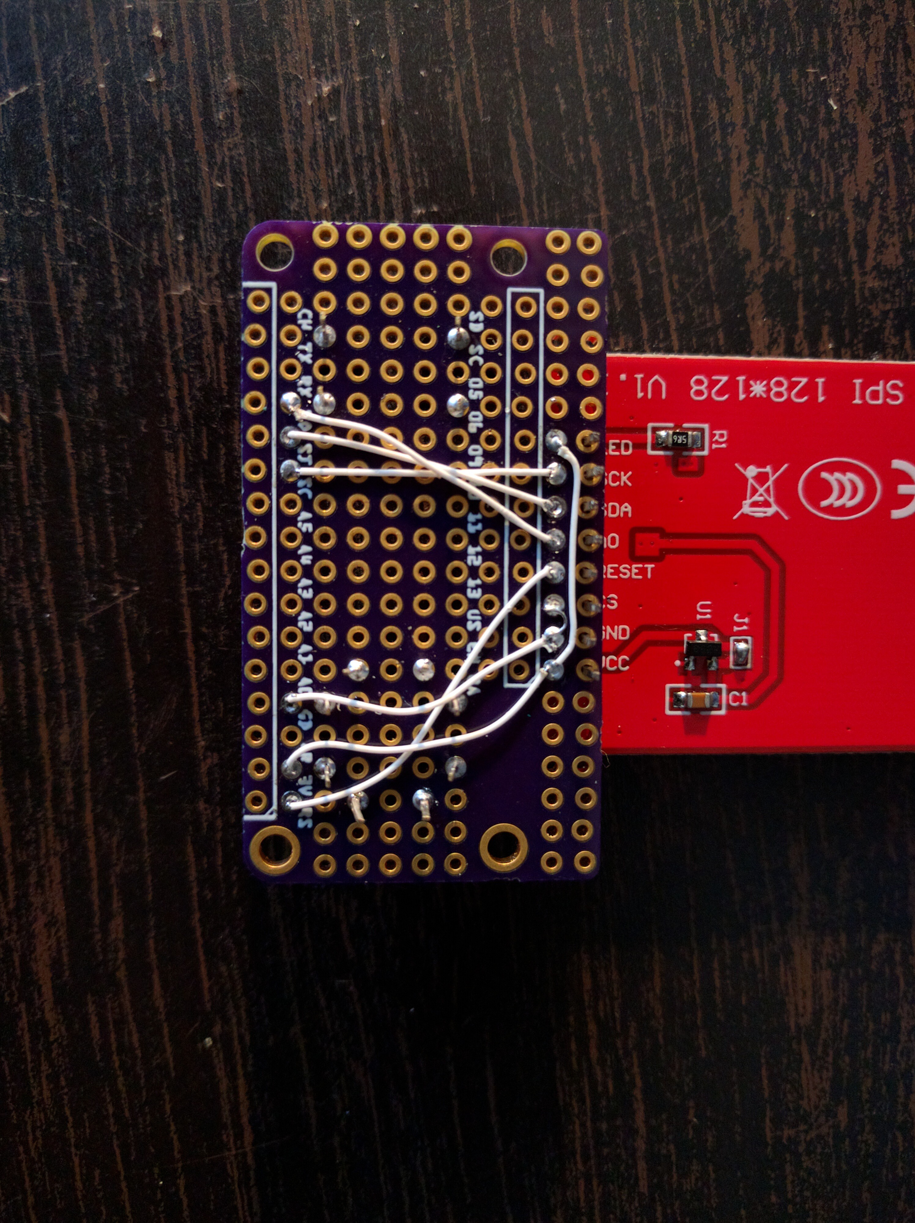
I wired it to the SPI pins of the feather, with CS pulled low permanently, RST connected to feather's reset, and LED pulled up.
![]()
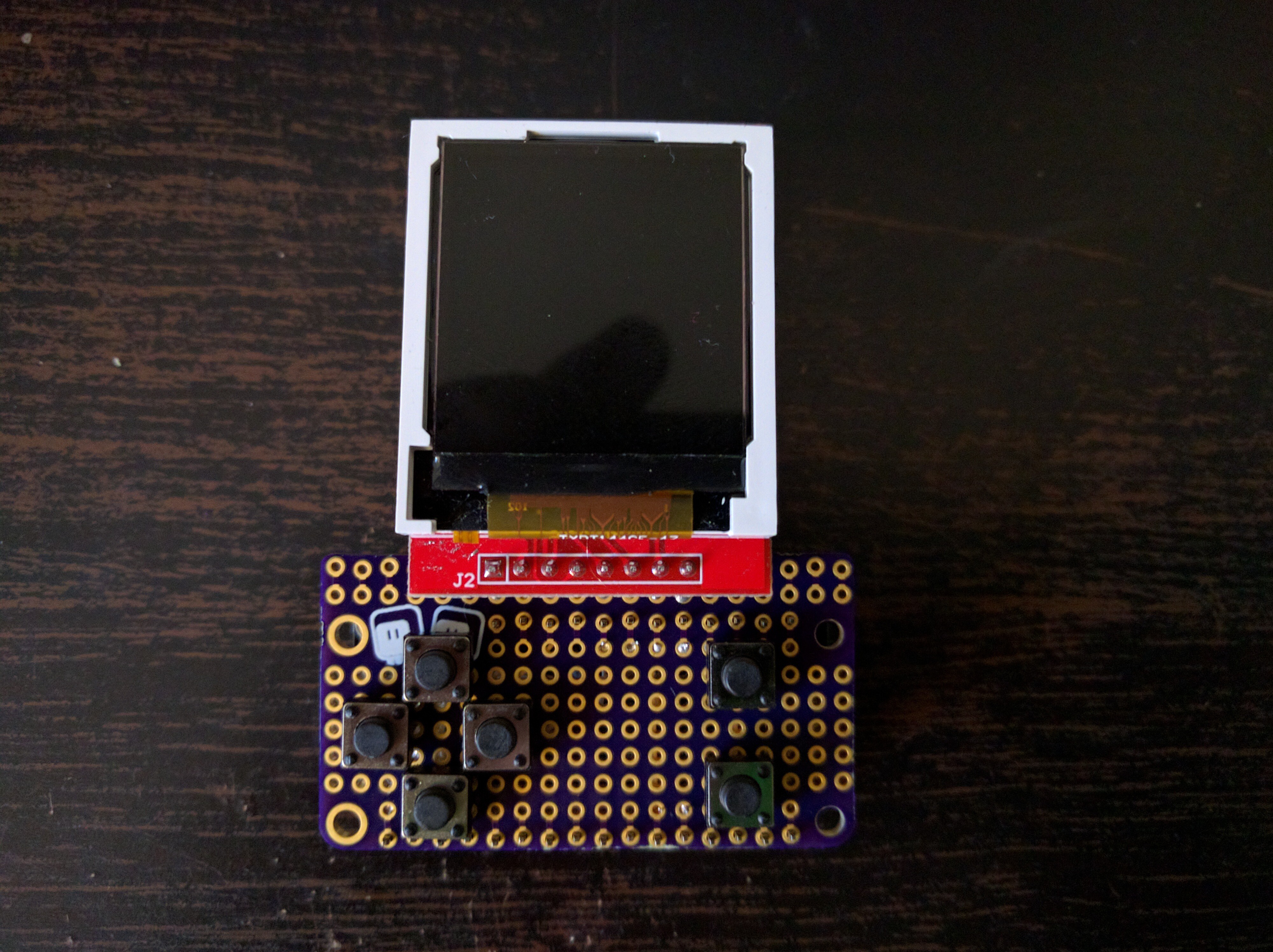
Then I also wired the buttons — one side of each button goes to GND, and the other side to one of the digital pins.
![]()
And that's it. Add some pin headers, and plug it into the feather:
![]()
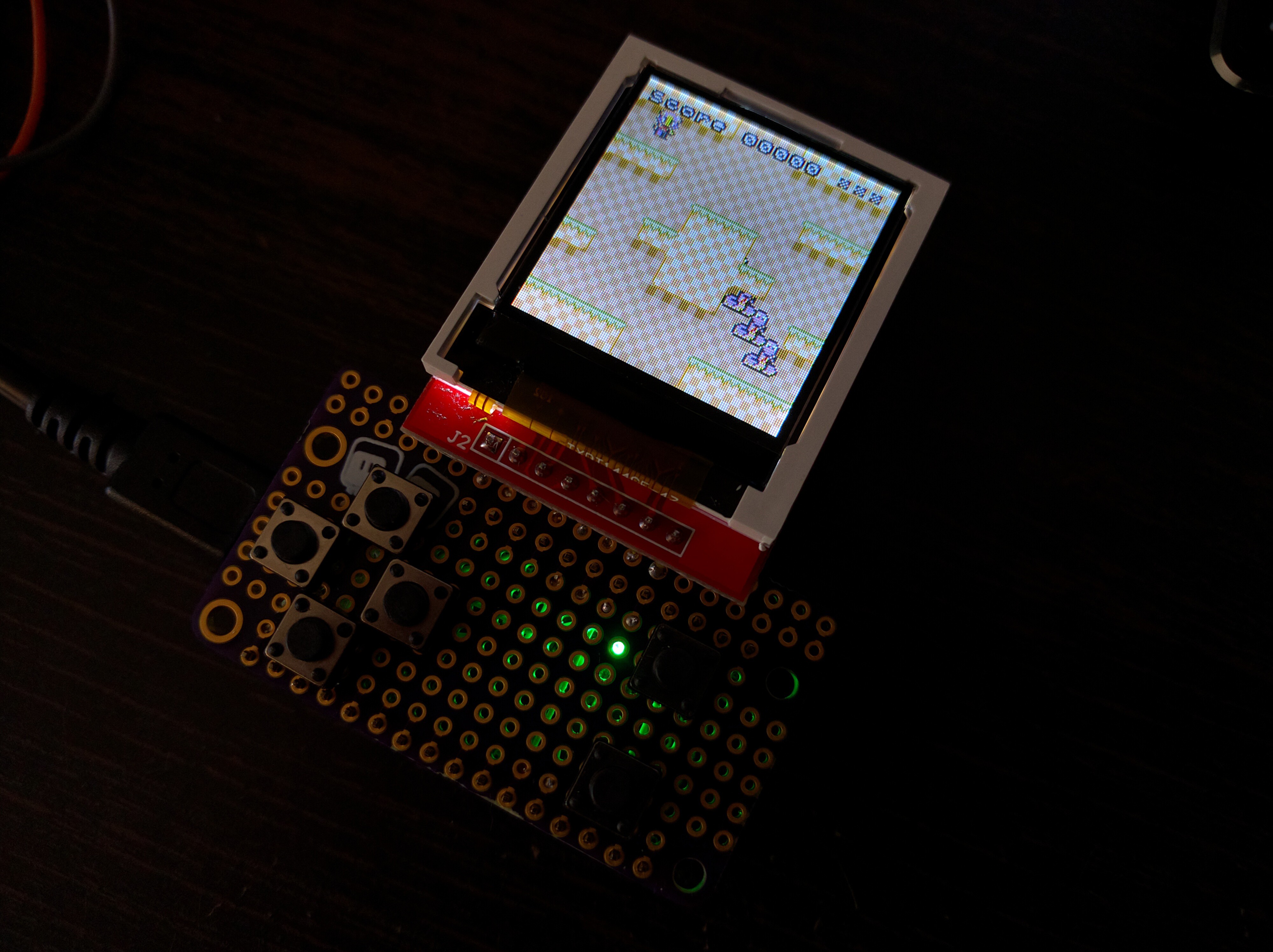
Next, I had to compile CircuitPython with my library enabled, and provide custom initialization code:
import board
import digitalio
import busio

import st7735r
import gamepad


K_X = 0x01
K_DOWN = 0x02
K_LEFT = 0x04
K_RIGHT = 0x08
K_UP = 0x10
K_O = 0x20


dc = digitalio.DigitalInOut(board.MISO)
spi = busio.SPI(clock=board.SCK, MOSI=board.MOSI)
spi.try_lock()
spi.configure(baudrate=23000000, polarity=0, phase=0)
display = st7735r.ST7735R(spi, dc, 0b110)
buttons = gamepad.GamePad(
    digitalio.DigitalInOut(board.D6),
    digitalio.DigitalInOut(board.D11),
    digitalio.DigitalInOut(board.D12),
    digitalio.DigitalInOut(board.D9),
    digitalio.DigitalInOut(board.D10),
    digitalio.DigitalInOut(board.D5),
)
(Since that module doesn't use the MISO pin, I used it for D/C). I uploaded my work-in-progress demo game, and voila, it works!
![]()
UPDATE: I had to make two changes compared to these photos. One, I forgot a wire from the fire buttons to the GND, and two, I now connected the CS pin to D13, instead of directly to GND.
-
The Case for a Case
11/11/2017 at 16:53 • 0 commentsJust before going on a two week vacation, I decided to try and see what I can do in terms of a case for this device. Why do I even need a case? Well, there are two reasons:
- To protect the glass (but not gorilla-glass) screen from scratches, so that I can carry it in my pocket,
- To protect the battery both mechanically and electrically from random objects in that pocket.
It's connected with the fact that I want to use a bigger LiPo battery than the 40mAh button cell battery I use right now.
With those goals in mind, what are my options?
- Use an existing, commonly available container of roughly the right size.
- Make the case out of layers of laser-cut transparent acrylic.
- 3D-print it, possibly adding laser-cut transparent acrylic as screen protection.
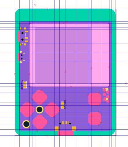
To see which of those options would be the best, I exported the PCB to Inkscape and prepared a model of the device, with all buttons, switches, sockets and the screen marked.
![]()
Then I tried to fiddle with it a bit, trying to come up with the layers for the laser-cut case. I immediately stumbled on a problem: the power switch (and also the reset switch, but that one could only have a hole to be pressed with a paperclip) only sticks out of the PCB very little — about 1mm. That means that the wall of the case can't be thicker than that, or that it needs to add some kind of an extension of the switch's knob. The USB port has a similar problem, but fortunately in this case it's more like 2mm, so it's not so bad.
There is also another problem if I decide to go for thin walls — the front panel needs cutouts for the buttons, and those pretty much touch the edge of the PCB, making this arrow-shaped corner of the panel, where the only mounting screw is, very fragile and easy to break off...
That's the status for now. I will probably keep thinking about this during my vacation, and will try something when I get back.
-
Hardware Version 4 and Sound
11/09/2017 at 20:49 • 0 commentsThe PCBs arrived from @oshpark today (I can't thank them enough for all the help I'm getting from them, including the coupons and fast shipping), so time to assemble the next hardware version. This time there were no surprises, the board seems to work.
This new version has the buttons spaced a bit farther apart from each other, which makes assembly much easier. It also has an audio amplifier and a tiny speaker. Since I'm still waiting for the 4x4mm speakers to arrive, I used a bigger SMD speaker for now for tests, and it's pretty loud! The small speaker will probably be much quieter, but I think it will still be good enough.
![]()
I still need to connect the battery and test the charging circuit, but I don't expect much trouble there — the first version has that working well.
-
Built-in Sprites
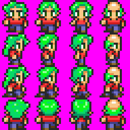
11/06/2017 at 20:10 • 0 commentsThe RAM memory is quite limited on the SAMD21, which means that you can only load about 4 or 5 banks of graphics at once. But there is some free flash memory in the custom CircuitPython firmware, so we can put some stock graphics in there. So I've been working a little on drawing the character sprites for that:
![]()
The colors are all funny, because I tried to make them distinct, so that you can easily re-color the sprites by custom palettes (a palette is only 32 bytes, while a bank is 2048). I'm trying to standardize the color positions in the palette too, so that you can use the same palettes for recoloring multiple banks.
The characters are mostly inspired by the GameBoy, SNES and NES classics, though they are not exact copies of any game in particular. They should retain the general feel, though.
-
Extra Characters
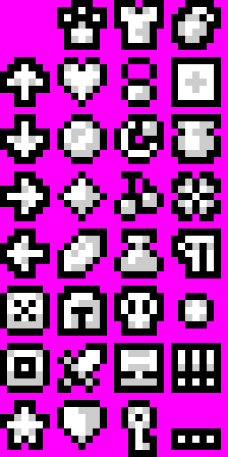
11/05/2017 at 17:35 • 1 commentInitially, my font file contained only 96 characters, ignoring the "control characters" that appear in the first 32 entries of the ASCII table. I realized that this is a waste, and decided to extend my font file to cover all 128 characters, and put some special things in the first 32 glyphs. Here's what I came up with:
![]()
The first four are arrows — always useful. Then there are icons for the two fire buttons this console has — useful when asking the player to press them. Then there is a number of random stuff that you might want to display on a status bar or in the inventory. Finally, some extra punctuation.
I'm not sure how useful this will turn out to be and if I wouldn't be much better off if I used that space for accented characters from a few European languages — but I can never cover all the languages anyways. In the worst case I can change it, and the users can always provide their own custom fonts too — there is a script in the repository for generating the script data from a BMP file.
-
Text Layers
11/04/2017 at 19:08 • 0 commentsToday I spent practically whole day coding, and added support for text layers to the tile engine. Behold:
![]()
Initially I didn't want to add another kind of layer just for this — it would have to be quite different than the grid layer, as the squares would be 8x8 pixels and the tile selection would need to be a whole byte, not 4 bits, plus I only need 4 colors in the font, so 2 bits per pixel...
So I got this idea: what if I make it a standard grid layer, with 16x16 tiles, but then generate a bank that has the text rendered on the tiles, and just display that. I quickly coded the proof of concept for that, and it worked, except it was horrendously slow and used a lot of memory.
So I decided to go for a new layer type after all. Since I only use 128 charcters from ASCII, I made the highest bit switch between two parts of the palette — so I can have text in two colors. I'm also not using the 32 control charcters at the beginning of ASCII right now, but I could put some extra characters in there, things like symbols for weapons and armor, arrows and buttons, HP and MP, hearts, stars, cat paws, etc.