 Ian Hanschen
The story so far...
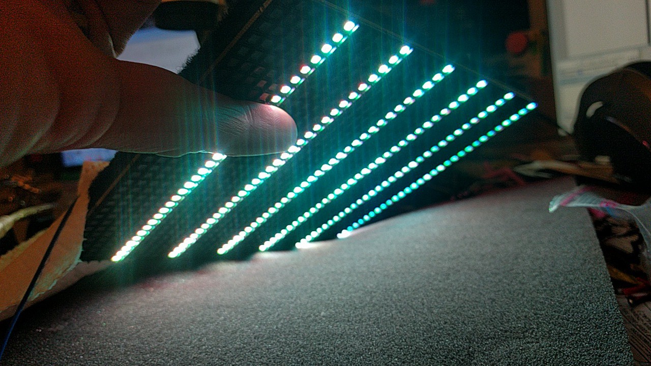
Update: Row scanning working.
Known/working:
- Building and loading via JTAG new firmware into the main FPGA. This firmware is starting from scratch, we don't understand much yet about the default Barco firmware, although we've dumped it.
- We understand the majority of how the board works and can display pixels (now on all rows), and communicate via the IN and OUT connectors (various protocols partially done, UART finished and working)
- Scanning out pixels to the main LEDs (and the 3 self-test LEDs on the back)
Unknown
- Don't know anything so far about the native Barco data format for driving the tiles without reflashing them first; this is going to be difficult without having a working Barco rig (controllers and head end) or insider info.
- Don't really know what the CPLD does internally, there's some communications between the Spartan and the CPLD that are captured but not figured out. It may not matter too much.
Unimplemented
- Daisychaining tiles (e.g. via LVDS)
- Temporarily (until powercycle) reprogramming a tile is easy enough with a JTAG interface, but a small amount more work is required to write a permanent image to the parallel flash onboard.
- A variety of housekeeping stuff; fan control, understanding the dot-correction calibration eeproms, and so on.
Panel LEDs
Contributors: @Richard Aplin, @modder_mike
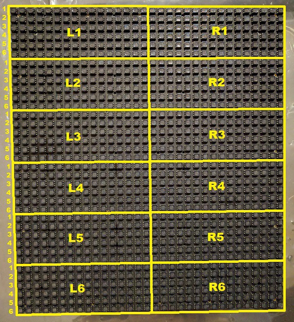
The panel is divided into twelve segments of 16x6. Each segment is driven by three Texas Instruments TLC5941 16-channel LED drivers. Each driver controls one color of the tri-color LEDs. The three drivers have their serial data cascaded, with the first controller in the cascade being Red, then Green, then Blue. Anode voltage is switched to each of the six rows of LEDs in sequence via a transistor controlled by the CPLD.
The 96 LEDs in the segment are controlled by only 16 driver channels by multiplexing the rows' LED anode voltage (TLC5941 switches the cathode side). Each of the 36 rows has a transistor between the panel's +4.5V input and the LED anodes. All like-numbered rows' transistors are connected to a common control pin on the CPLD. The CPLD cycles through them in sequence as instructed by the FPGA, synchronized with the incoming display data.
Take care when rewriting HDL for the FPGA. Because the LEDs are expecting to be run at only 1/6 duty cycle, they may theoretically be damaged if they are not cycled as quickly by user HDL. (For experimenting, consider using the calibration LEDs on the rear of the panel, which are not multiplexed.)
There are three I2C devices on the LED panel, an EEPROM, a temperature sensor and an ambient light sensor used for brightness calibration.
Most of the LED driver control pins are brought out to the data connector by way of two buffers. The remaining signals (SOUT for each driver string) are fed to the CPLD.
Back Panel Connectors
Contributors: @Richard Aplin, @modder_mike, @Chankster, @Ian Hanschen
Input connector (TE AMP 206486-2 - mates with 206485-1)
| Pin | Function | FPGA Pin | FPGA LVDS Pair | FPGA Direction |
| 1 | +VIN. Connected to a Linear LTC1778. Recommend 14.5-24V. | - | - | - |
| 2 | - | 117 | 2N | IN |
| 3 | - | 120 | 3N | IN |
| 4 | - | 113 | 1N | OUT |
| 5 | - | 112 | 1P | OUT |
| 6 | GND | - | - | - |
| 7 | - | 116 | 2P | IN |
| 8 | - | 119 | 3P | IN |
| 9 | No discernible connection | - | - | - |
Output connector (TE AMP 206433-2, mates with 206434-1)
| Pin | Function | FPGA Pin | FPGA LVDS Pair | FPGA Direction |
| 1 | +VOUT | - | - | - |
| 2 | GND | - | - | - |
| 3 | - | 134 | 2P | OUT |
| 4 | - | 131 | 1N | OUT |
| 5 | - | 128 | P | IN |
| 6 | - | 135 | 2N | OUT |
| 7 | - | 130 | 1P | OUT |
| 8 | - | 129 | N | IN |
JTAG Pinout
Contributors: @Richard Aplin
Tap C103 for JTAG VREF. FPGA JTAG configured for 2.5V, do not use pin 4 - your FPGA will be harmed.
| Pin | Function | Pin | Function |
| 1 (near R103) | TCLK | 2 | GND |
| 3 | TDO | 4 | ☠️ 3.3V ☠️ |
| 5 | TMS0 | 6 | GND |
| 7 | NC | 8 | GND |
| 9 | TDI | 10 | GND |
Xilinx XC3S250E FPGA Pinout
Contributors: @modder_mike, @Richard Aplin
Note that the SRAM and the Flash share an interface bus. Also note that the JTAG interface is 2.5V logic.
| Pin | Function | Pin | Function |
| 1 | PROG_B (Pullup to +2.5V) | 73 | GND |
| 2 | LED_L1_SIN | 74 | SRAM_A16; FLASH_A15 |
| 3 | LED_L2_SIN | 75 | SRAM_A15; FLASH_A14 |
| 4 | LED_L3_SIN | 76 | SRAM_A14; FLASH_A13 |
| 5 | LED_R1_SIN | 77 | SRAM_A13; FLASH_A12 |
| 6 | Not yet mapped | 78 | Not yet mapped |
| 7 | LED_R2_SIN | 79 | VCCO_1 (+3.3V) |
| 8 | LED_R3_SIN | 80 | VCCINT (+1.2V) |
| 9 | VCCINT (+1.2V) | 81 | SRAM_A12; FLASH_A11 |
| 10 | LED_XERR | 82 | SRAM_A11; FLASH_A10 |
| 11 | GND | 83 | FLASH_RESET# |
| 12 | Not yet mapped | 84 | Not yet mapped |
| 13 | VCCO_3 (+3.3V) | 85 | SRAM_A10; FLASH_A9 |
| 14 | LED_L4_SIN | 86 | SRAM_A9; FLASH_A8 |
| 15 | LED_L5_SIN | 87 | SRAM_A8; FLASH_A7 |
| 16 | LED_L6_SIN | 88 | SRAM_A7; FLASH_A6 |
| 17 | LED_R4_SIN | 89 | Not yet mapped |
| 18 | Not yet mapped | 90 | GND |
| 19 | GND | 91 | SRAM_A6; FLASH_A5 |
| 20 | LED_R5_SIN | 92 | SRAM_A5; FLASH_A4 |
| 21 | LED_R6_SIN | 93 | SRAM_A4; FLASH_A3 |
| 22 | LED_CAL_SIN | 94 | SRAM_A3; FLASH_A2 |
| 23 | CPLD_PIN_44 | 95 | Not yet mapped |
| 24 | CPLD_PIN_6 | 96 | SRAM_A2; FLASH_A1 |
| 25 | I2C_SCL | 97 | SRAM_A1; FLASH_A0 |
| 26 | I2C_SDA | 98 | SRAM_A0; FLASH_DQ15/A-1 |
| 27 | GND | 99 | GND |
| 28 | VCCO_3 (+3.3V) | 100 | VCCO_1 (+3.3V) |
| 29 | Not yet mapped | 101 | Not yet mapped |
| 30 | VCCAUX (+2.5V) | 102 | VCCAUX (+2.5V) |
| 31 | SRAM_CE# | 103 | SRAM_WE#; FLASH_WE# |
| 32 | LED_XLAT | 104 | FLASH_CE# |
| 33 | LED_MODE | 105 | FLASH_OE# |
| 34 | LED_BLANK | 106 | Not yet mapped |
| 35 | SRAM_OE# | 107 | FLASH_RY/BY# |
| 36 | Not yet mapped | 108 | JTAG_TMS |
| 37 | GND | 109 | JTAG_TDO |
| 38 | Not yet mapped | 110 | JTAG_TCK |
| 39 | VFAN_ENABLE | 111 | FAN_TACHOMETER |
| 40 | Not yet mapped | 112 | INPUT_CONN_PIN_5 |
| 41 | Not yet mapped | 113 | INPUT_CONN_PIN_4 |
| 42 | VCCO_2 (+3.3V) | 114 | Not yet mapped |
| 43 | SRAM_BHE# | 115 | VCCINT (+1.2V) |
| 44 | SRAM_BLE# | 116 | INPUT_CONN_PIN_7 |
| 45 | VCCINT (+1.2V) | 117 | INPUT_CONN_PIN_2 |
| 46 | GND | 118 | GND |
| 47 | Not yet mapped | 119 | INPUT_CONN_PIN_8 |
| 48 | Not yet mapped | 120 | INPUT_CONN_PIN_3 |
| 49 | VCCO_2 (+3.3V) | 121 | VCCO_0 (+2.5V) |
| 50 | SRAM_IO7; SRAM_IO15; FLASH_DQ7 | 122 | VFAN_ADJUST |
| 51 | SRAM_IO6; SRAM_IO14; FLASH_DQ6 | 123 | CPLD_PIN_8 |
| 52 | SRAM_IO5; SRAM_IO13; FLASH_DQ5 | 124 | CPLD_PIN_3 |
| 53 | SRAM_IO4; SRAM_IO12; FLASH_DQ4 | 125 | CPLD_PIN_2 |
| 54 | SRAM_IO3; SRAM_IO11; FLASH_DQ3 | 126 | CPLD_PIN_5 |
| 55 | GND | 127 | GND |
| 56 | OSC_40MHz | 128 | OUTPUT_CONN_PIN_5 |
| 57 | Not yet mapped | 129 | OUTPUT_CONN_PIN_8 |
| 58 | SRAM_IO2; SRAM_IO10; FLASH_DQ2 | 130 | OUTPUT_CONN_PIN_7 |
| 59 | SRAM_IO1; SRAM_IO9; FLASH_DQ1 | 131 | OUTPUT_CONN_PIN_4 |
| 60 | DIAGNOSTIC_LED_YELLOW | 132 | CPLD_PIN_43 |
| 61 | GND | 133 | GND |
| 62 | DIAGNOSTIC_LED_RED | 134 | OUTPUT_CONN_PIN_3 |
| 63 | SRAM_IO0; SRAM_IO8; FLASH_DQ0 | 135 | OUTPUT_CONN_PIN_6 |
| 64 | VCCO_2 (+3.3V) | 136 | Not yet mapped |
| 65 | VCCAUX (+2.5V) | 137 | VCCAUX (+2.5V) |
| 66 | FLASH_A19 | 138 | VCCO_0 (+2.5V) |
| 67 | FLASH_A18 | 139 | LED_SCLK |
| 68 | FLASH_A17 | 140 | LED_GSCLK |
| 69 | Not yet mapped | 141 | Not yet mapped |
| 70 | SRAM_A17; FLASH_A16 | 142 | CPLD_PIN_42 |
| 71 | DIAGNOSTIC_LED_ORANGE | 143 | CPLD_PIN_41 |
| 72 | DONE (Pullup to +2.5V) | 144 | JTAG_TDI |
I²C Bus
Contributors: @modder_mike
| Address | Hex | Part | Remarks |
| 0b0111001x | 0x39 | Taos TSL2560 | Device maker/model unverified |
| 0b1001000x | 0x48 | Analog Devices AD7416 | LED Panel temperature sensor |
| 0b1001001x | 0x49 | Analog Devices AD7416 | Control Board temperature sensor |
| 0b1010000x | 0x50 | Atmel AT24C512 | LED Panel EEPROM |
| 0b1010001x | 0x51 | Atmel AT24C512 | Control Board EEPROM |
LED Panel Connectors
Contributors: @modder_mike
Power connector:
| 4 | GND |
| 3 | GND |
| 2 | +4.56V |
| 1 | +4.56V |
Data Connector:
| CPLD_PIN_6* | 60 | 30 | VIN |
| CPLD_PIN_44* | 59 | 29 | VIN |
| CPLD_PIN_43* | 58 | 28 | GND |
| CPLD_PIN_42* | 57 | 27 | I2C_SDA |
| CPLD_PIN_41* | 56 | 26 | I2C_SCL |
| LED_GSCLK | 55 | 25 | LED_BLANK |
| LED_XLAT | 54 | 24 | LED_MODE |
| CPLD_PIN_8* | 53 | 23 | CPLD_PIN_2* |
| CPLD_PIN_5* | 52 | 22 | CPLD_PIN_3* |
| +3.3V | 51 | 21 | +3.3V |
| +3.3V | 50 | 20 | +3.3V |
| +3.3V | 49 | 19 | +3.3V |
| +3.3V | 48 | 18 | +3.3V |
| GND | 47 | 17 | GND |
| GND | 46 | 16 | LED_XERR |
| GND | 45 | 15 | LED_CAL_SIN |
| LED_R6_SIN | 44 | 14 | GND |
| GND | 43 | 13 | LED_R5_SIN |
| LED_R4_SIN | 42 | 12 | GND |
| GND | 41 | 11 | LED_L6_SIN |
| LED_L5_SIN | 40 | 10 | GND |
| GND | 39 | 9 | LED_L4_SIN |
| LED_R3_SIN | 38 | 8 | GND |
| GND | 37 | 7 | LED_R2_SIN |
| LED_R1_SIN | 36 | 6 | GND |
| GND | 35 | 5 | LED_L3_SIN |
| LED_L2_SIN | 34 | 4 | GND |
| GND | 33 | 3 | LED_L1_SIN |
| GND | 32 | 2 | GND |
| GND | 31 | 1 | LED_SCLK |
*CPLD pins are not yet mapped to functions. CPLD functions include cycling through rows, routing SOUT data from LED drivers, and six pins mapped to transistors scattered across the board with yet unknown function.
As we solidify our analysis, @Ian Hanschen will add documentation (digested from the logs) here. Sometimes I'll lift the whole log. I don't have everything here yet, will keep adding more as we go.