 Christoph Tack
Hardware
For this proof of concept any Arduino compatible board with at least two GPIO's can be used. The more GPIO's on your board, the more connections can be tested.
I used a NUCLEO-F103RB for this project. Any Arduino compatible board should work.
Male/male jumper wires have been used to make connections between the pins.
Custom shield
It's left up to the implementer to design custom shields. If you want to test UTP-cables, you might want to design a shield with two 8pin modular jacks of which each pin is wired out to GPIO of the Arduino.
Firmware
can be found on Github.
User communication
The user interface has been kept as minimal as possible. A 9600baud serial port is used:
- Press 'l' (small L) to instruct the Arduino to Learn the connections of the "golden cable harness"
- Press 't' to instruct the Arduino to Test the connections on an unknown cable
Algorithm
The algorithm uses only the digital pin functionality of the Arduino, i.e. GPIOs. This makes it easy to port between MCU-architectures.
If you want to test complicated harnesses with a lot of connections, you could use an Arduino Mega. The algorithm also allows you to skip GPIOs that are not part of the cable harness.
Each GPIO is an index in the connection matrix. This connection matrix stores the connections between the pins. Each index contains the lowest GPIO-number the current GPIO is connected to: e.g. GPIO3 is connected to GPIO6 and GPIO7, then matrix[3]=3, matrix[6]=3, matrix[7]=3.
The connections are checked by setting a master GPIO as output and pulling it low. All consecutive GPIO's are set as input-pull-up. The value of all these inputs is read. If the value is low, it means that pin is connected to the master GPIO. The index in the connection matrix for that input will be set to the master GPIO number. When all inputs are read, the master GPIO is set as input and the following GPIO becomes master GPIO, upon which the process is repeated.
Once the connection matrix is completely filled in, it's cell-by-cell compared to the original connection matrix. Any differences will be output on the serial port.
This simple process uses simple IO-logic, so cable harnesses with built in capacitors or transformers can not be tested in this way.
Note on testing flat cables
Assembling flat cables with IDC-connectors is quite prone to errors. Especially if you don't own the proper tools. For testing these cables there's a much easier way which only involves a few passive components.
The nature of flat cables is such that short circuits can only be made to adjacent wires. This makes things easier. With a power supply, a resistor and an LED it's possible to test flat cables
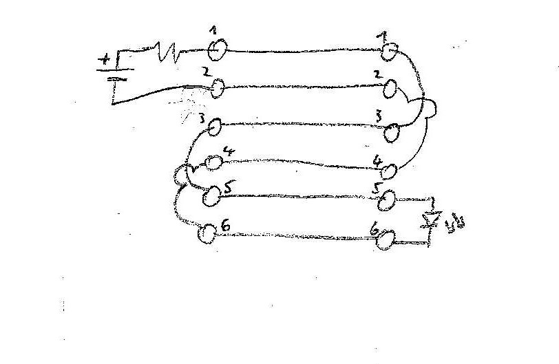
In the sketch above you can see the principle. There's a test connector with 6 pins on the left side. This could be a 2x3 box header. There's an identical connector on the right side. These two connectors are soldered on your test fixture. All connections are present on your test fixture, except for the horizontal connections between the left and right connector, these are made by the "cable-under-test".
By plugging in a "cable-under-test", the connections in the middle of the sketch are made: 1-1, 2-2, 3-3, ...
If all is well, the LED will light. If there's an open, it's clear that the current path is broken and the LED will be off. What about short circuits? As there can only be short circuits between adjacent traces, let's pick a random short circuit : between wire 3&4. The current will flow to wire 1, then through wire 3, then through wire 4 and by wire 2 back to the power supply. The LED is essentially short circuited and will not light. The resistor on the power supply is there to limit the current in those cases.