 Ben Lim
Full schematics and EAGLE files are provided in the Files Section.
0%
0%
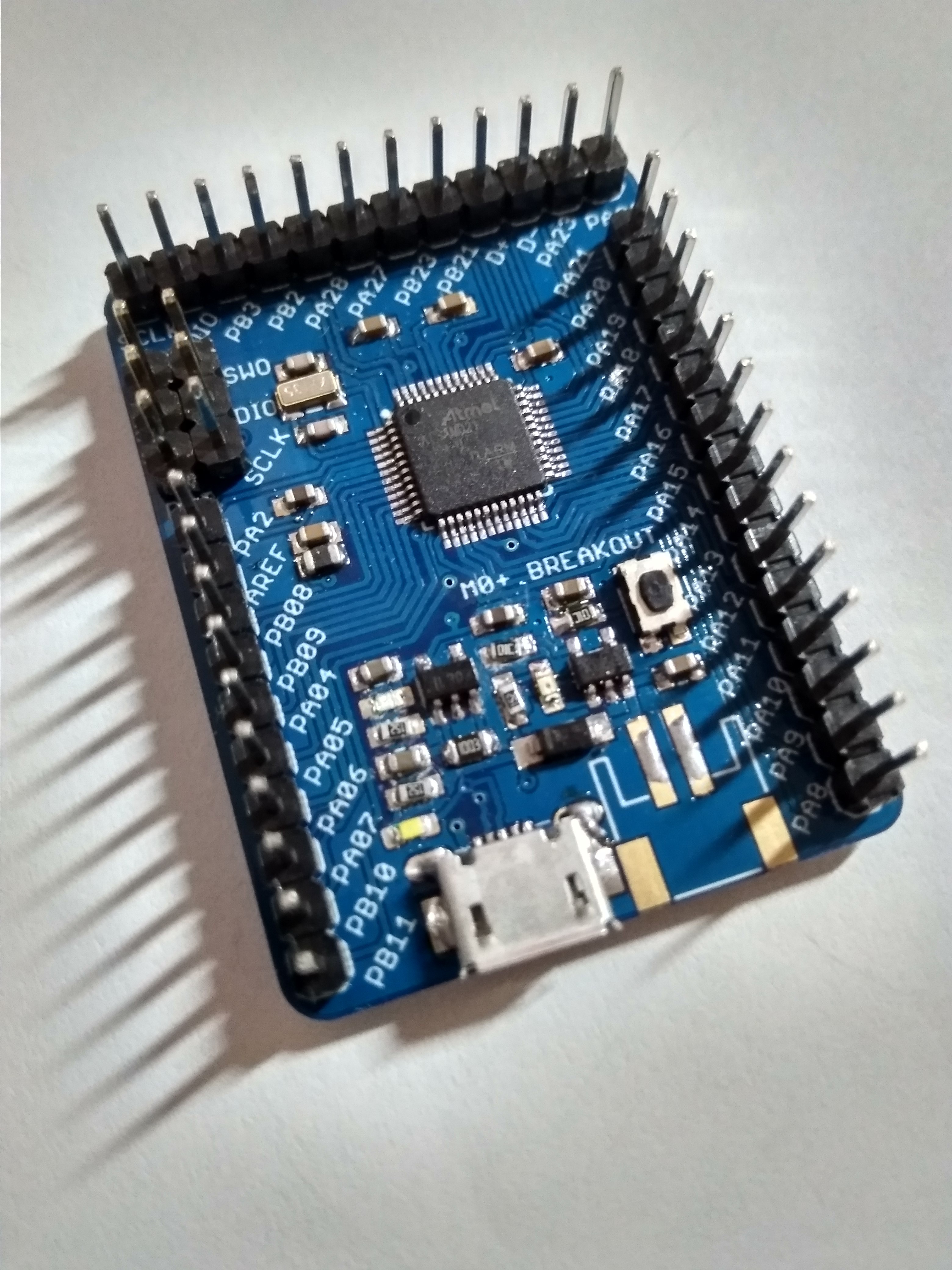
M0+ Breakout Board
A breakout board for the Cortex M0, SAMD21G18A for use with Arduino.
Become a Hackaday.io member
Already have an account? Log in.
Just one more thing
To make the experience fit your profile, pick a username and tell us what interests you.
Pick an awesome username
hackaday.io/
Your profile's URL: hackaday.io/username. Max 25 alphanumeric characters.
Pick a few interests
Projects that share your interests
People that share your interests
 SHAOS
SHAOS
 maehem
 Kirroslink
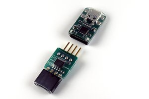
 Saimon
First, thank you for posting your circuit. I am trying to make it.
One of the ICs on the schematic is labeled "MCP73831T" which is a PMIC battery manager. However the description is "fixed voltage regulator". The schematic has the pins of a SPX3819. That is confusing but the most confusing is the Vout of this part goes thru a 10K resistor to ground. Would appreciate how you intended to use this. Thank you.