Close
0%
0%

Match Box ESP Dash Button

ESP8266 + Coin Cell + Match Box = Dash Button

Similar projects worth following
I built a simplistic dash button equivalent from a minimal set of components at minimal cost (less than 2$).
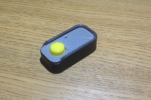
The casing is a decorated match box, pushing it, turns on the ESP, which connects to WIFI and then executes a command of my choice.

I started out wanting to build a simple dash-button that I can push that would ring my phone so I could easily locate it. I designed a transistor circuit to turn on the ESP and make sure it keeps turned on until its done doing its thing and then powers off automatically. Needless to say, it got a bit complicated relatively quickly.

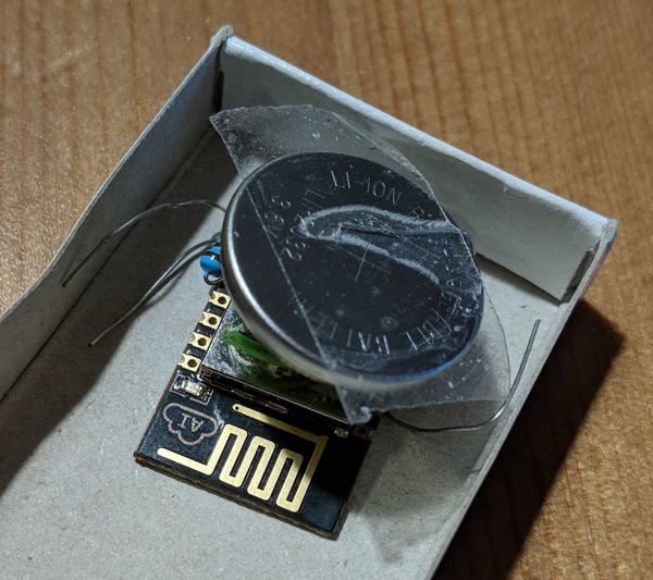
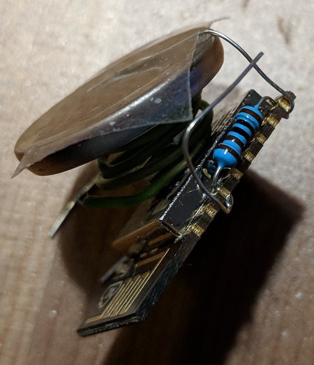
Then I realized, I can have this much simpler. Instead of a complex circuit, I can reduce this to essentially only the ESP: The battery is separated from the device using a self-made spring. When pushing it, it directly powers the ESP which is still happy with 3.7V or even 4.2V, so I don’t even need a voltage regulator. The ESP does its thing, and uses its LED to signal when its done, so I can stop pushing the battery down. It’s slightly crude, but the simplicity is overwhelming.

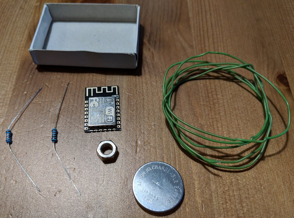
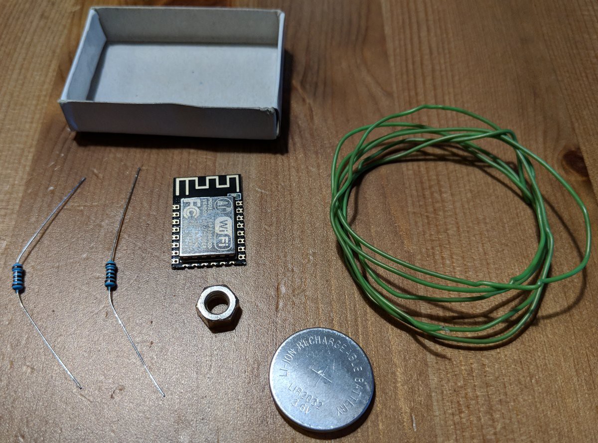
Here’s a picture of the components I needed:
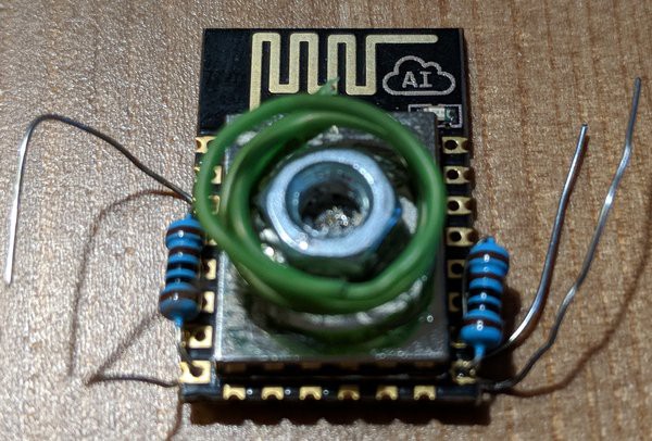
Assembled it looks like this:
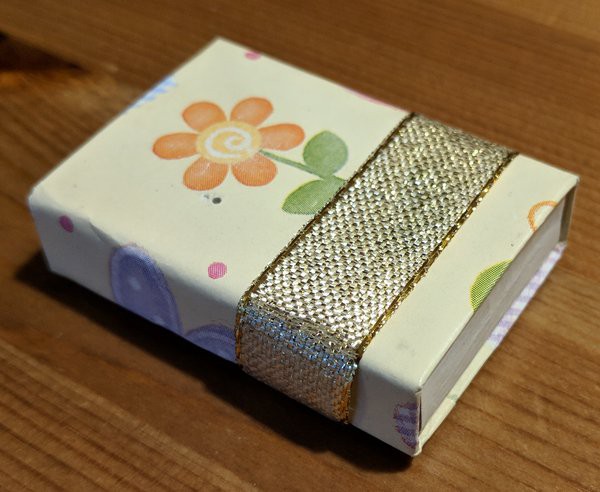
Finally, some gift-wrapping utensils make it look pretty:
  • 1 × ESP8266
  • 1 × Match Box
  • 2 × 1k resistor
  • 1 × 3.7V coin cell

  • 1
    Gather the components
    1. A bare ESP8266 module
    2. 2 1k resistors
    3. A 3.7V coin cell
    4. Insulated wire to form the spring
    5. A nut to give the spring some space
    6. A match box for casing + some gift wrapping paper for decoration
    7. A soldering iron + solder
  • 2
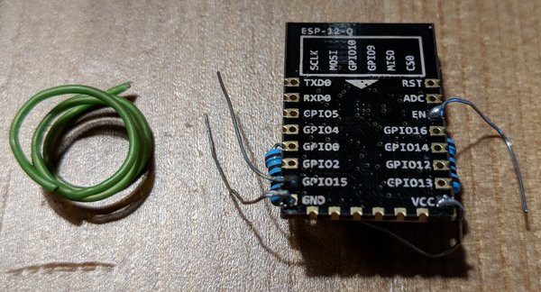
    Connect the resistors

    The resistors are permanently needed, so we may connect them already and solder them.

    VCC and EN are connected, as are GPIO15 and GND.

    The excess wire of VCC will later be used to hold the coin cell.

    I also leave the other excess wires present as it allows me to easily connect external power supply for firmware flashing and they automatically hold the device in place within the match box.

  • 3
    Attach the spring mechanism

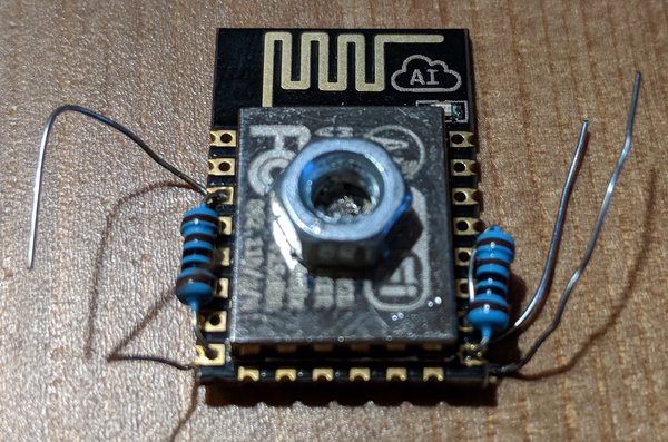
    Use the insulated wire to form a spring (as shown above) by wrapping it around a round object, e.g. a pen. The diameter should be slightly larger then the spacing nut.

    Incidentally, the casing of the ESP is connected to GND, so we can just solder the nut on it.

    Now place the spring around it. Make sure it still separates the coin cell from the nut when put on top.

View all 6 instructions

Enjoy this project?

Share

Discussions

Similar Projects

Does this project spark your interest?

Become a member to follow this project and never miss any updates