I found a simple 555 based oscillator circuit that has controls for adjusting the frequency and pulse width that should be able to operate the speed controller on Electro Schematics. They have both the parts list and circuit board layout to use for making one. You can also buy a ready built unit on Ebay with a display showing the frequency and pulse width on a small screen for $3.50 that uses push buttons instead of rotary knobs.
http://www.electroschematics.com/5834/pulse-generator-with-555/
 Chris
Chris
 Frank Herrmann
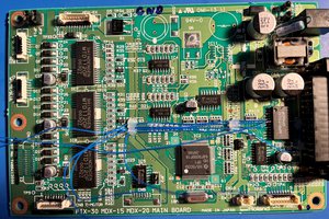
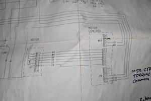
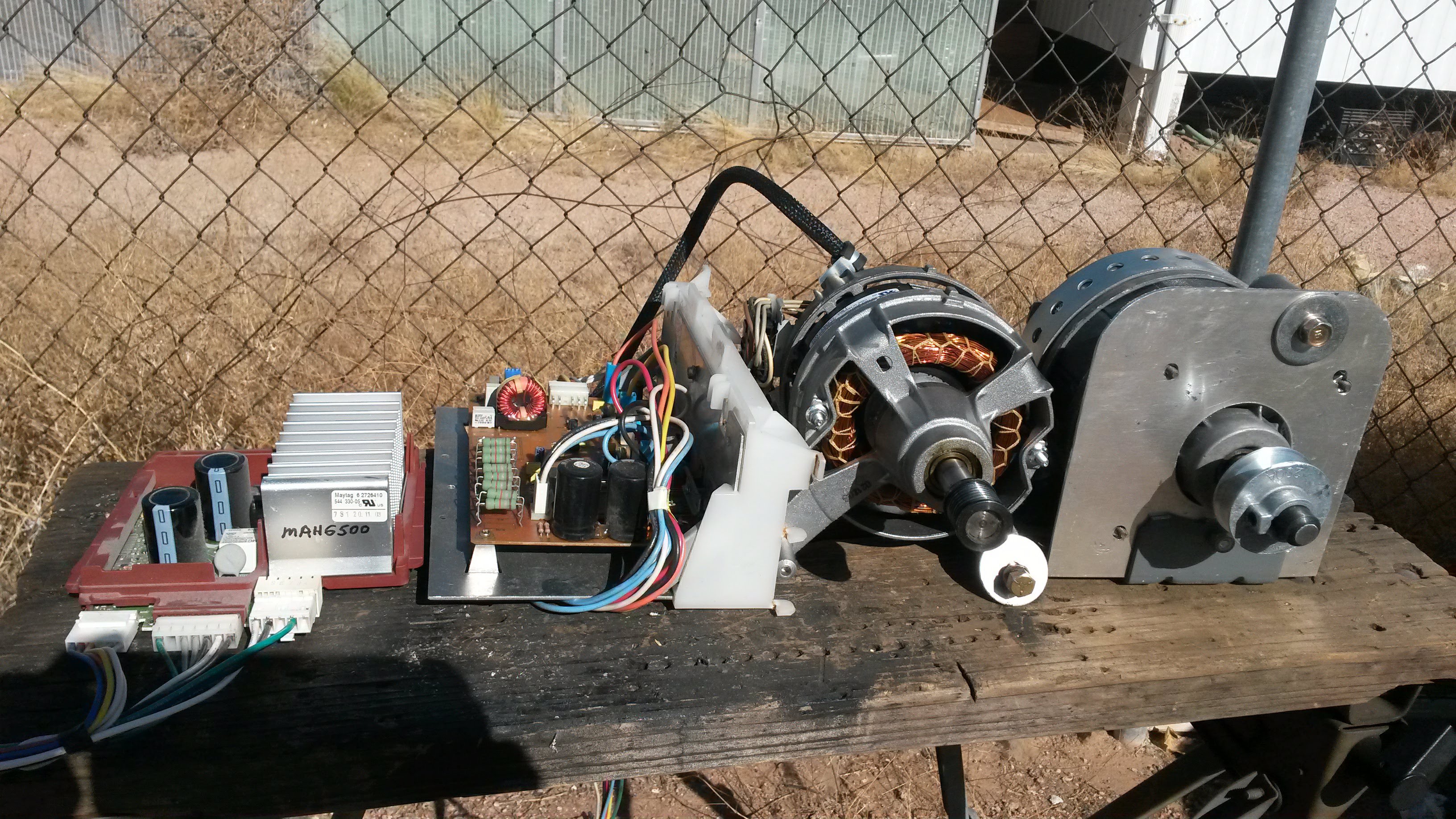
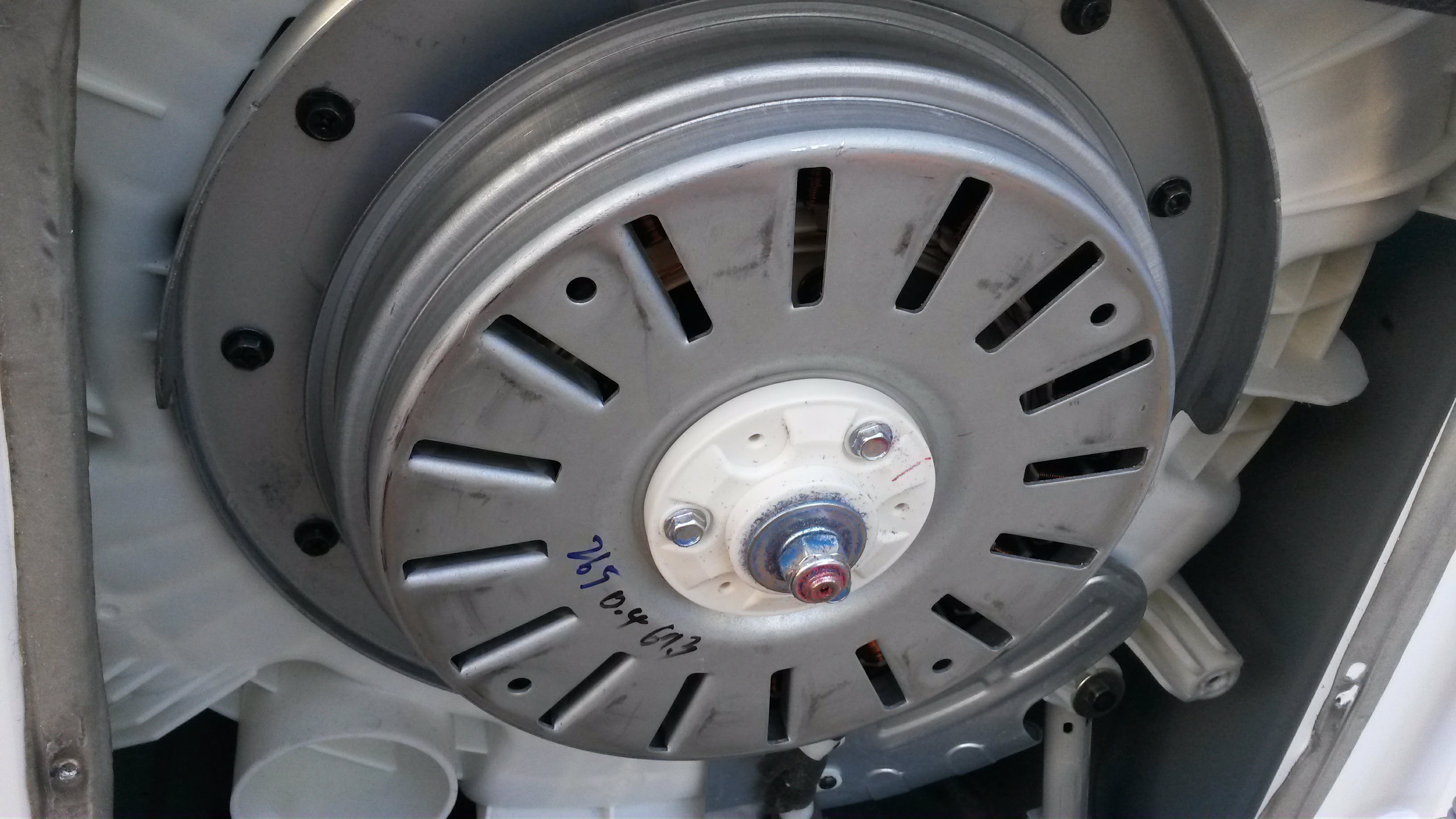
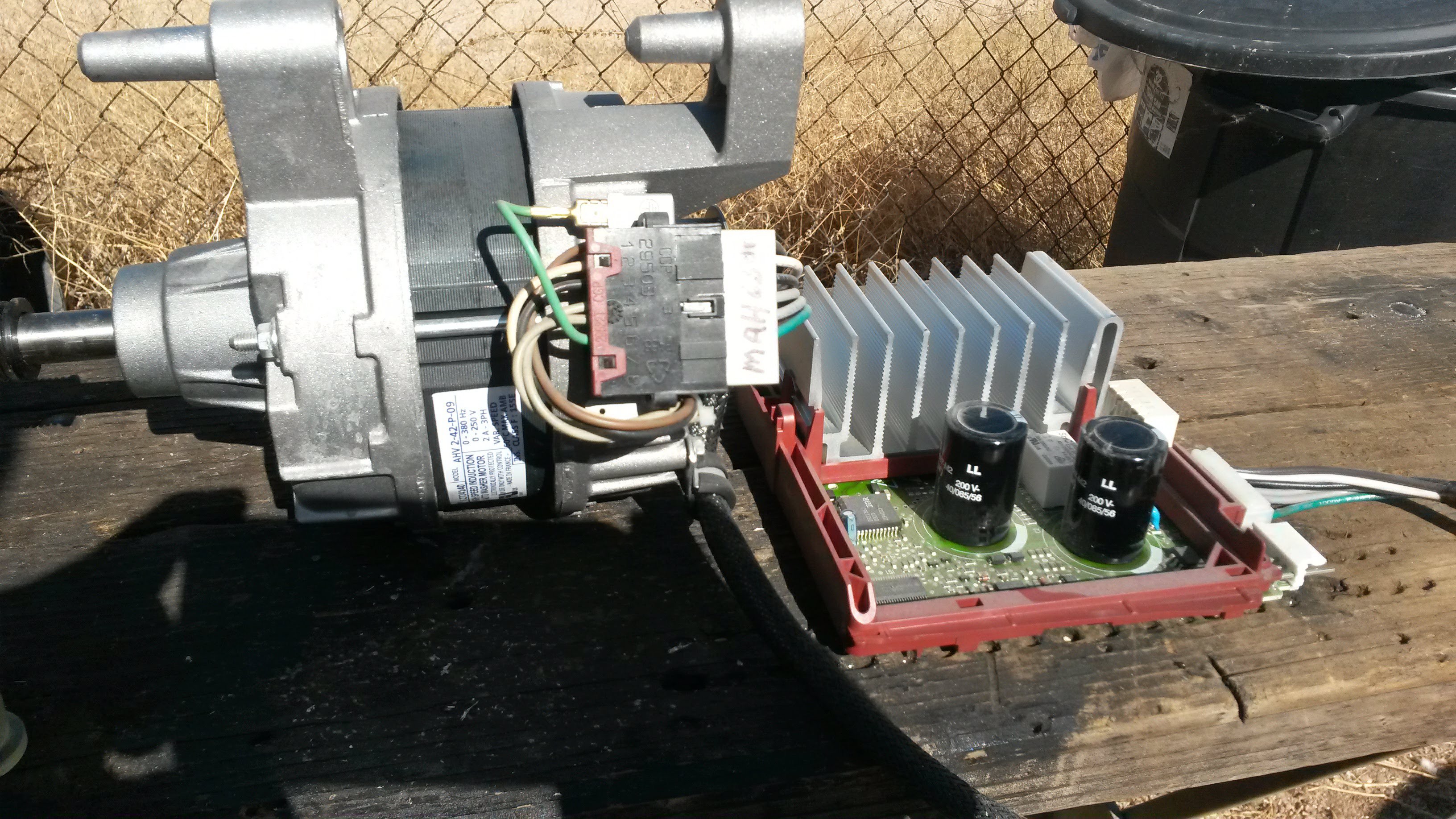
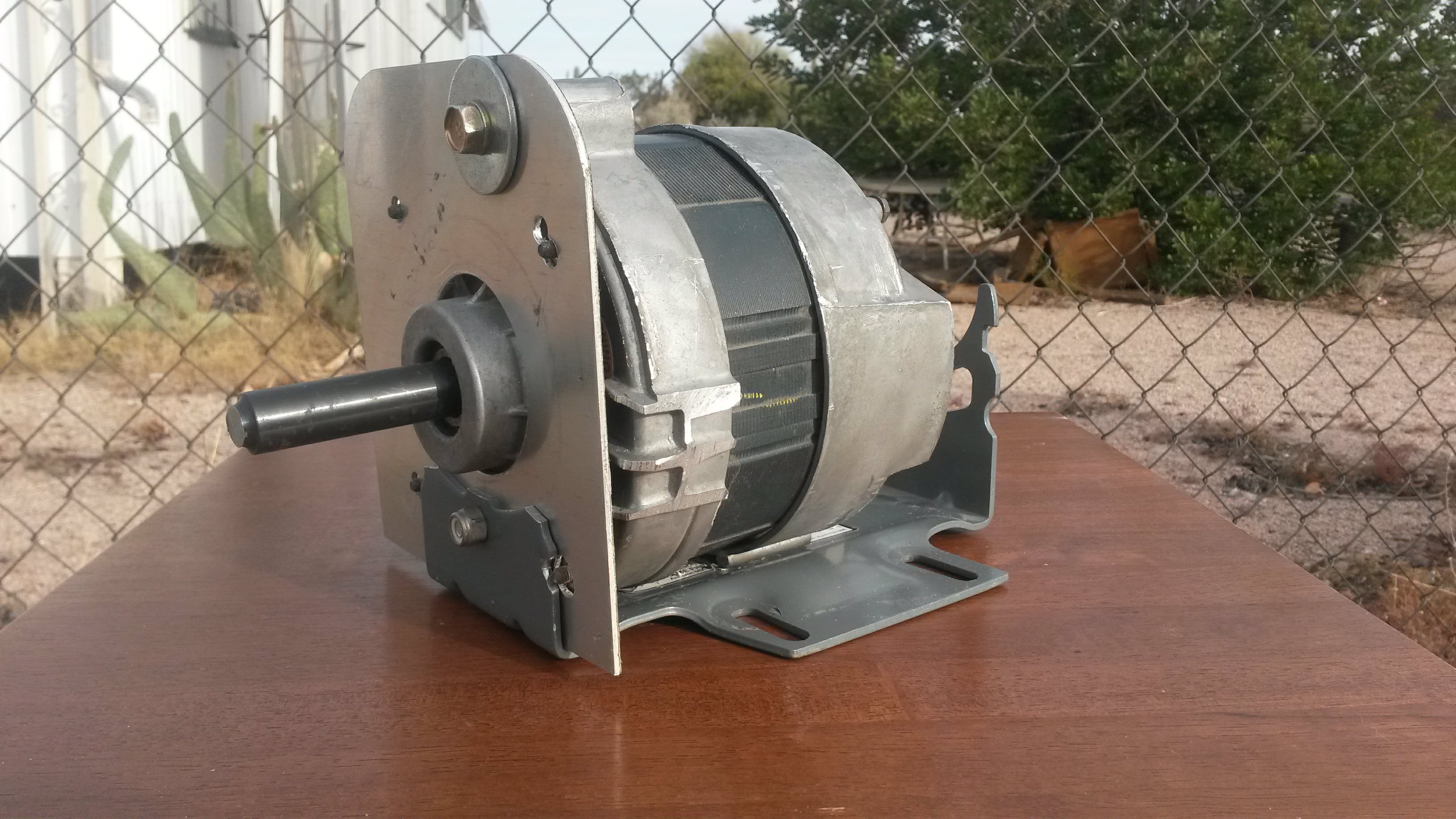
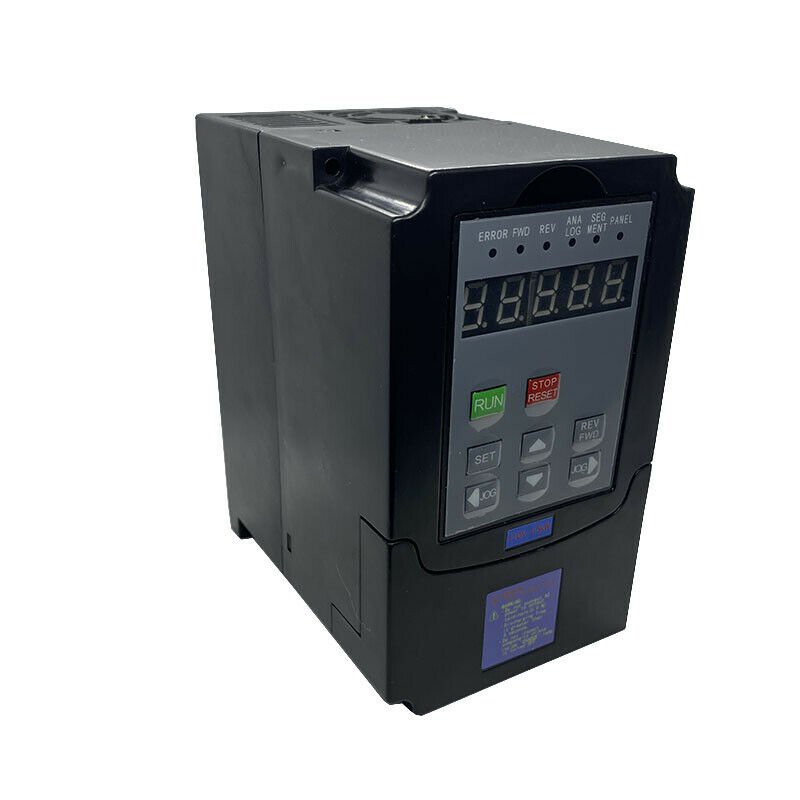
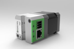
I have finally completed my Maytag Neptune Switched Reluctance Induction Motor controller with Jerry Trantow's help. I have mounted the motor and controller on my Eastwood "Bead Roller" along with a 100 : 1 worm gear reduction box and the Neptune 14:1 micro belt drive giving a total 1400:1` reduction of the 22,000 Rpm motor to give a useful variable final drive speed of ~ 16 Rpm. The controller uses the Maytag motor controller circuit board and a 10 VDC power supply to drive the programmable XY-PWM-1 Pulse Width controller found on e-bay. I will if I can figure out how to down load a circuit drawing (DWG) and 3 photos of the completed unit sans the safety guarding (yet to be fabricated).
Paul