Description
I salvaged the motor and motor controller from a scrapped Maytag MAH7500 Neptune front loading washing machine. These are relatively easy to find. I have seen other projects online that reuse the motor with an external VFD but have not seen an explanation of reusing the motor controller. This project is intended to illustrate how I figured out how to use the motor controller and motor.
The service schematics comes with the machine and is also available online. You should look up the exact details for the washer you find but these are mass produced units and I expect all Maytag Neptune or similar models will use nearly identical systems.
You can easily check the motor and controller by pulling the JP4 six pin connector to the motor controller. This enables a diagnostic mode and If the motor and controller are good the system will spin slowly. (50 RPM?) If it spins, salvage the motor, motor controller, and the wire harness connectors attached to motor controller. I recommend grabbing the belt and the pulley attached to the tub. I think I tossed my pulley which I regret as this is a high speed motor and you will probably want to use the mechanical reduction.
System
The motor is a high frequency induction motor and the motor controller converts AC line to DC to three phase motor power. Line voltage goes to MN4.
The service schematic only shows three other signals going to the motor controller. MTR CTRL TACH, TORQUE PWM, and WTR CONTROL SIGNAL COMMON. Looking at the motor controller board I saw some CNY17 opto isolators near JP4 which leads me to believe the signals are opto isolated.
Control Signal Description
MTR CTRL TACH
The schematic shows a tachometer signal coming from the motor and into the motor controller. This signal appears to be available and opto-coupled at the JP4 connector pin 5 red wire labeled MTR CTRL TACH. I used a pull up resistor to 5V and observed this signal on a scope. I spun the motor by hand two quick revolutions and saw eight pulses come out. So this is a 4 pulse per revolution tach signal. I expect this signal could go straight into a micro controller with an internal pull up. When the motor is being driven I do see some noise on this line. If this persists when I clean up the wiring, I will filter this signal.
TORQUE PWM
This is the only control signal input. My first attempt was driving this with a 0-5V square wave and varying the frequency. Nothing happened until I exceeded 70hz at which point the motor spun up fast. Like 375 hz or 22500 RPM fast. At that point, I realized the control signal is proportional to duty cycle and not frequency. With no load on the motor it will spin at max frequency with a 50% duty cycle. My function generator will only go to 20% duty in the square wave mode. Using the pulse mode, I found the motor will start up when the frequency is >70 hz and you bump the duty >4%. With no load on the motor, it only requires approx 3% to keep the motor spinning at a couple hundred RPM. At 4% the motor will ramp up to full speed.
WTR CONTROL SIGNAL COMMON
This appears to be the ground signal for the MTR CTRL TACH and TORQUE PWM signals. These signals may be opto coupled inside the motor controller. This signal is NOT POWER COMMON.
Mechanical
Many applications for small electric motors use four pole motors (1750 RPM). The motor shaft has a 7/8" pulley and I think the (lost) pulley for the washer provided a 11:1 speed reduction which dropped the motor from 375 hz or 22500 RPM to about 2000 RPM. So if this is used to replace a standard motor you should probably keep the mechanical reduction.
Next Step
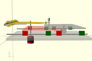
Now that I understand the TORQUE PWM signal and the MTR CTRL TACH feedback, I will use a micro controller with PID to control the variable speed system. This system will probably end up driving a drill press, belt sander, or small lathe. Correctly sized for the application, I should be able to achieve precise speed...
Read more »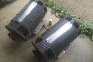
 Ampeater
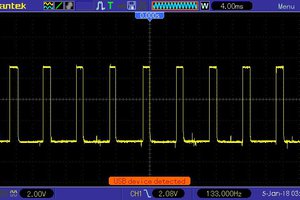
 Philip Ashmore
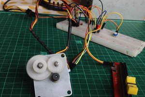
 KushagraK7
I got a pulley for a 5/8" shaft but it doesn't fit and I found the motor shafts to be metric. The older motor has a 17mm shaft and the newer one has 15mm. To get the pulley to fit the 17mm shaft I had to bore it out slightly.