 icstation
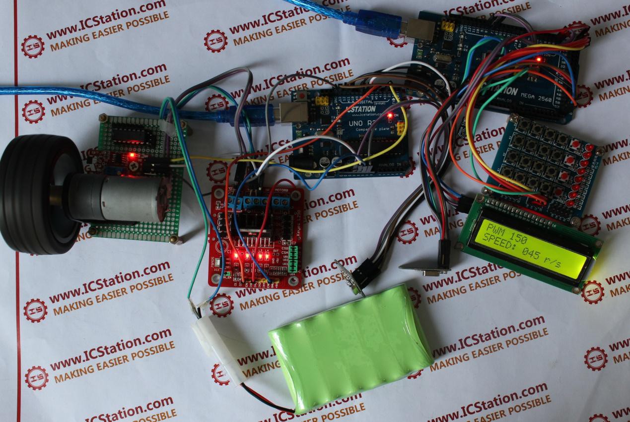
Functions:
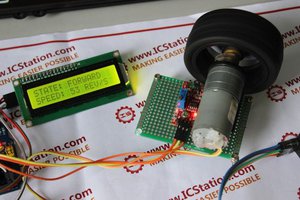
1)When initialize the sending part, the LCD1602 board displays the characters of the original PMW data and the speed which is with zero. The receiving part will control the wireless transmission of data and displays the real rotate
speed after the receiving part finished the initialization.
2) When the Receiving Module works, the rotate speed of the Motor will change according to the data which is transmitted by the sending part. The Holl Sensor Speed Measure Module begins to detect the rotate speed and the LED light of the Holl sensor lights. Meanwhile, the Wireless Module of the receiving part will send the detected rotate speed data back to the Sending part.
3) For the sending part, we need four keys (K0,K1,K2,K3) in the keyboard to change the speed of the motor. The associated functions of the four keys as following:
①Press the key KO for the first time, the motor moves as the first gear of speed; press the key KO again, the motor moves as the second gear of speed; the third time when we press the key KO, the motor moves as the third gear of speed; the,forth time when we press the K0,,the motor moves as the first gear of speed.
②Press the key K1, we can switch the rotate speed of increasing or reducing.
③Press the key K2, we can change the rotate speed to five more or less.
④Press the key K3, we can change the rotate speed to ten more or less.
Code for reference:
http://www.icstation.com/newsletter/eMarketing/NRF24L01_Control_Code.zip
Step 1: Components list:
1. 1×ICStation ATMEGA328 UNO V3.0 R3 Board Compatible Arduino UNO R3
2. 1×ICStation ATMEGA2560 Mega2560 R3 Board Compatible Arduino
4. 1×Dual H Bridge DC Stepper Motor Drive Controller for Arduino L298
5.1×1602A HD44780 Character LCD Display Module LCM Blue Backlight
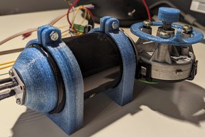
7.1×KY-024 Linear Hall Magnetic Module for Arduino AVR PIC
8.1×DC Motor Micro Motor Miniature D21mm X H25mm
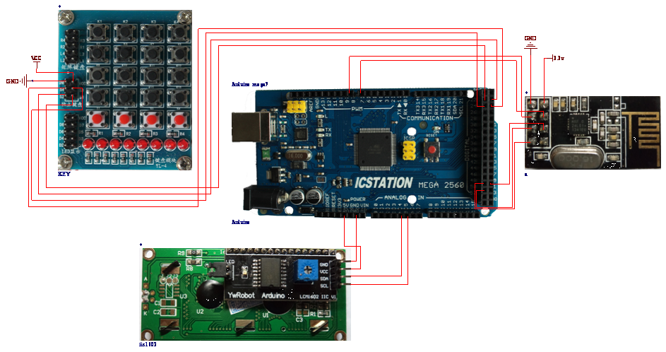
Step 2: Schematic Diagram
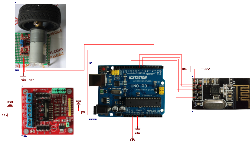
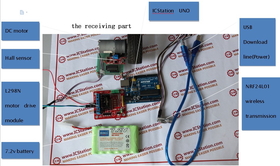
Step 3: The connection of receiving part
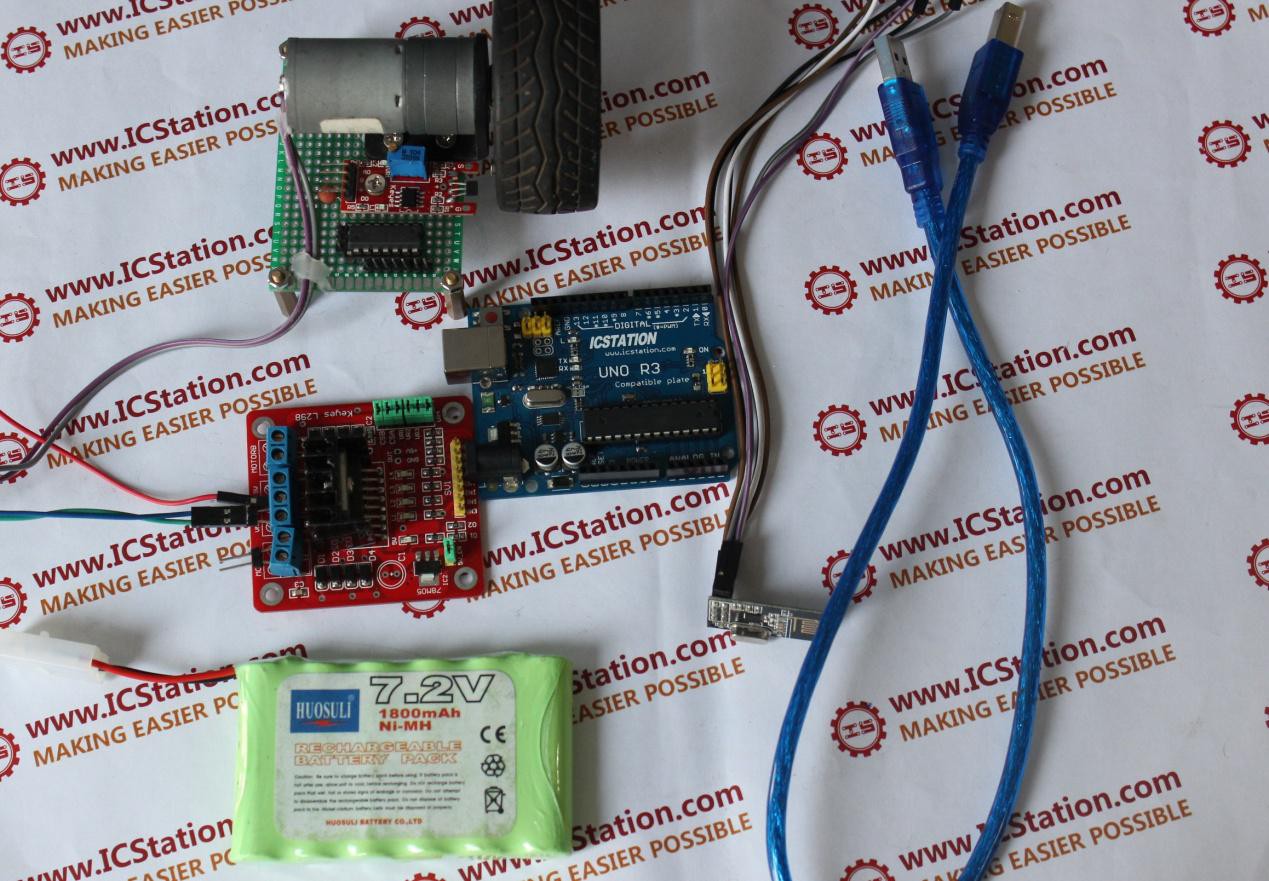
1.Connect the NRF24L01 Wireless Module to the ICStation UNO.
SCK--Digital pin 13 ;MOSI-- Digital pin 11 CS——Digital pin 7;
CS——Digital pin 8;MOSI-- Digital pin 12
2.Connect the L298N to the ICStation UNO
VMS—7.2V Anode;GND—Cathode INA—GND;
INB—VCC(5V);ENA—Digital pin 5
3.Connect the Hall Module to the ICStation UNO
DOUT—Digital pin 3
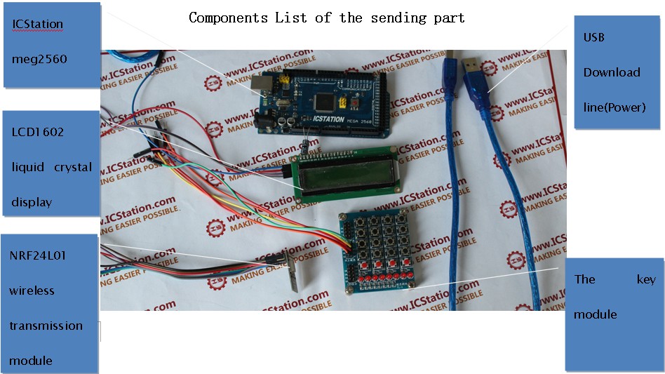
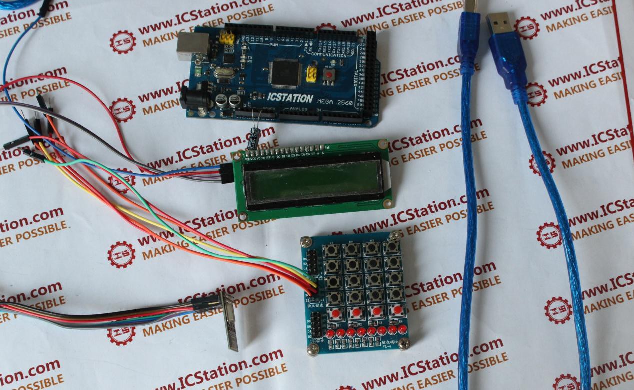
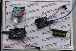
Step 4: The connection of sending part
1.Connect the NRF24L01 Wireless Module to the ICStation MEGA2560
SCK--Digital pin 52 ;MOSI-- Digital pin 51 MOSI--Digital pin 50;
CS——Digital pin 9 CE——Digital pin 8
2.Connect the 1602 LCD Module to the ICStation MEGA2560
SCL—A5 ;SDA—A4
3.Connect the keyboard to the ICStation MEGA2560
S1—Digital pin 22;S1—Digital pin 23 S1—Digital pin 24;S1—Digital pin 25
video to show effect:
http://youtu.be/Sup4UG2MwO0
 JP Gleyzes
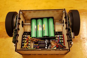
 shane.snipe