 zakqwy
Hot Garbage, as in poor product design decisions that I am finally fixing. I'm talking, of course, about the first NeuroBytes v0.8 power supply:
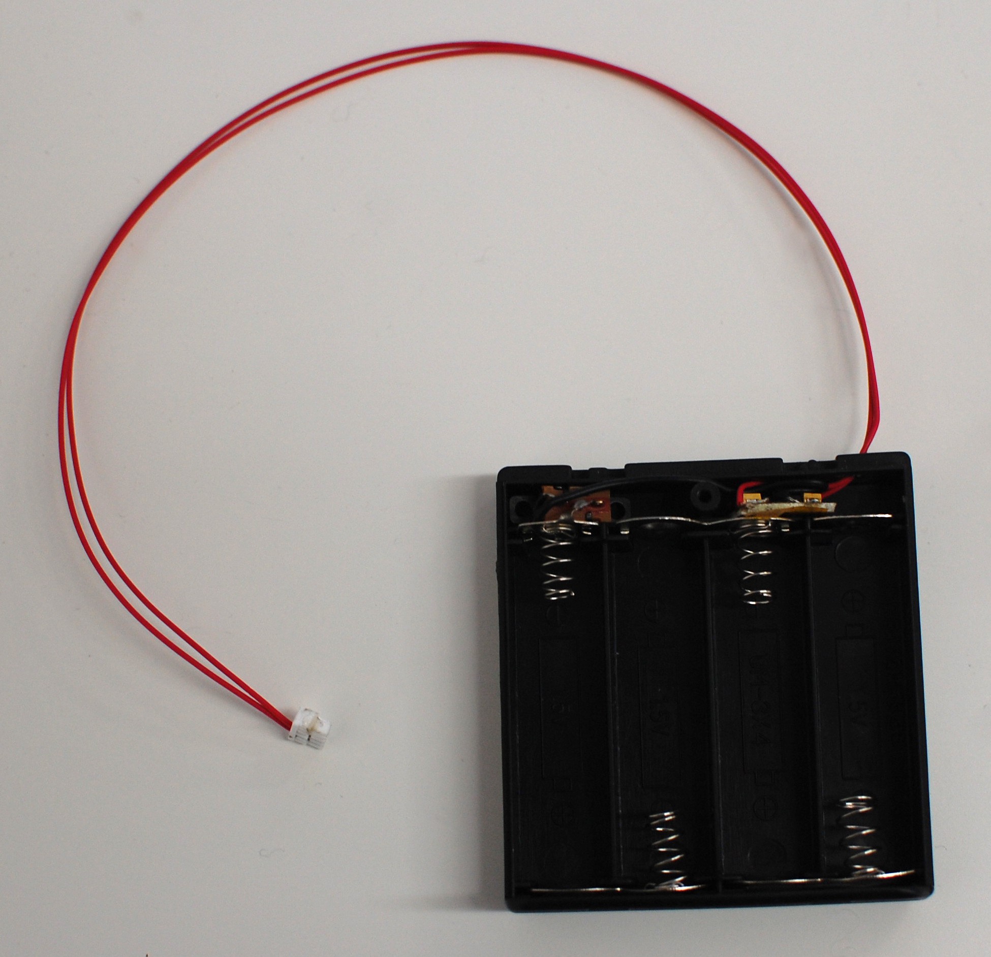
I covered the panicked construction of these power supplies in a previous log. Briefly, I needed a 5VDC power supply that was somewhat self-contained and JST GH compatible, so I bodged the boxes shown above together at the eleventh hour. They were Hot Garbage for any of a number of reasons; in particular, the slide switch was horrifically unreliable and had a nasty habit of pushing into the case after a few uses.
The move to on-board LDOs with NeuroBytes v0.91 meant the power supply boards became a good deal less complex. However, I still made some bad decisions with subsequent iterations:
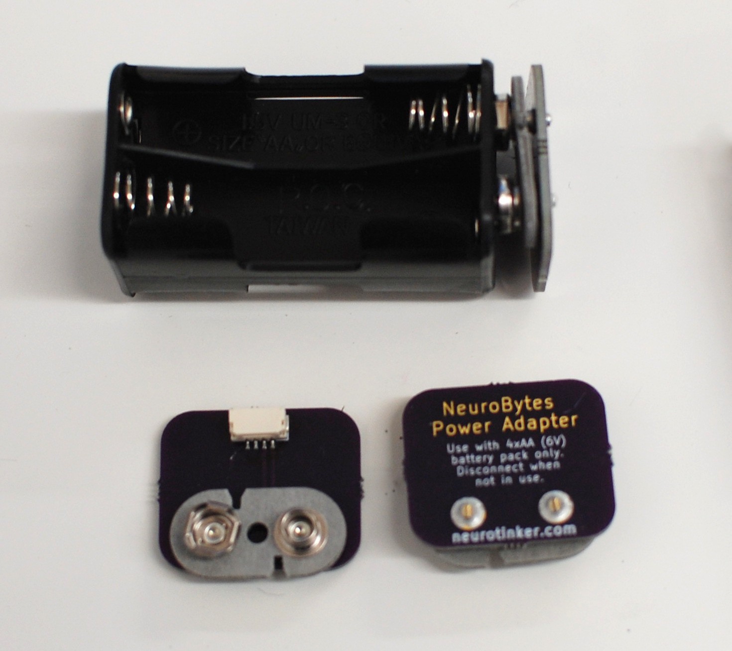
Above: Still not great. The 9vdc snap doesn't sit flat on the 4xAA pack which looks bad. Also, someone could easily hook up a 9vdc battery which wouldn't be great for any number of reasons. No, I won't take a better picture. Sorry.
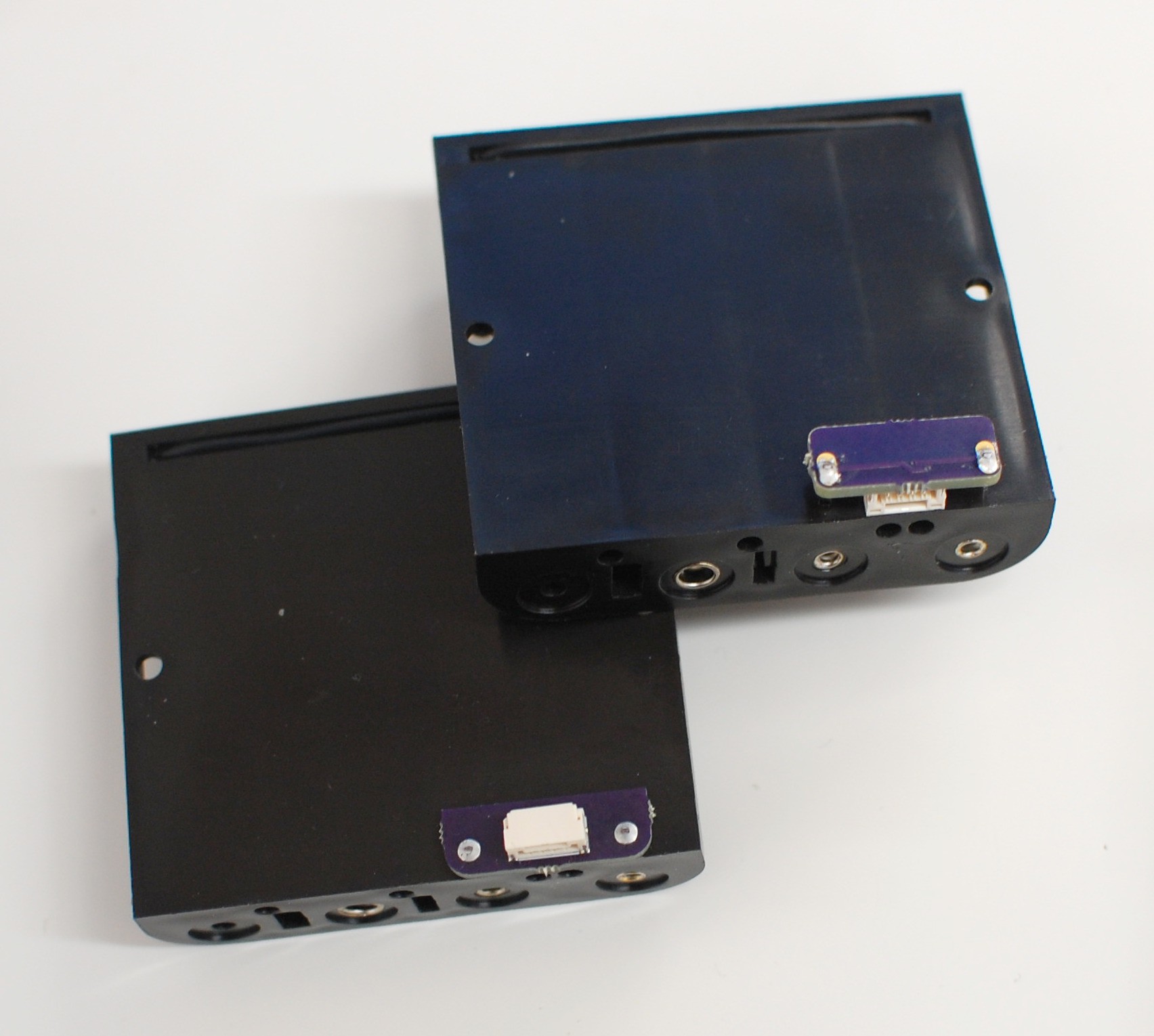
Above: Two similar minimalist options. I tried to make the board as small as possible to minimize cost. Yes, the top right iteration was backwards, so I could either turn the board around or flip it upside-down. Both of these designs were simple enough, but they're also prone to damage when stored loose in a box with heavy batteries installed. Also, the asymmetry means they don't sit flat on the table. A quick fix but in need of another revision.
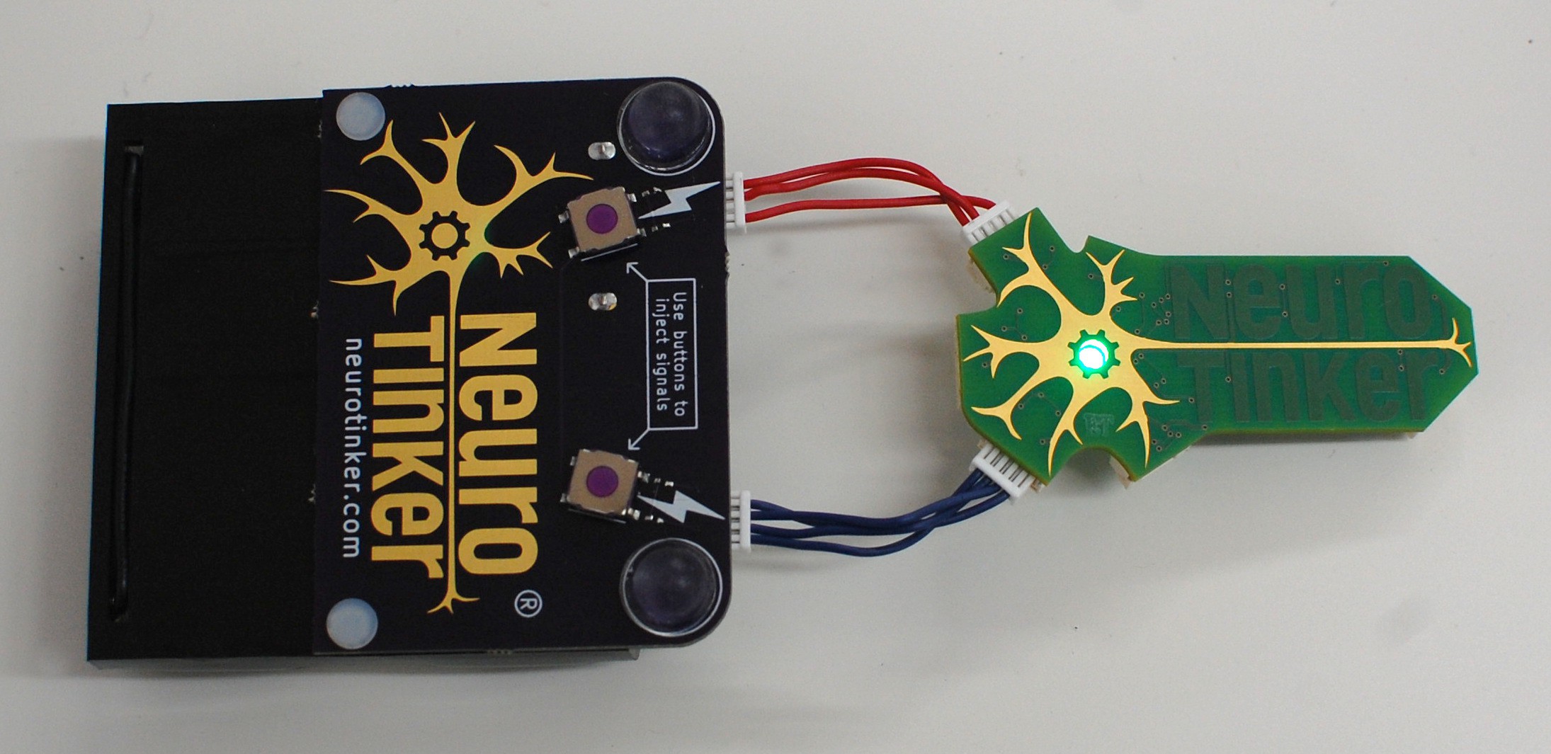 Above and below: Many important changes. For starters, I located a nylon rivet on McMaster that _precisely_ fits the two holes in the battery pack, and is sized right for 1/16" FR4. The rivets are incredibly secure and allowed me to expand the circuit board quite a bit. Secondly, I inset the JST GH connectors a bit; when cables aren't plugged in, they're somewhat protected by the board overhang and are less likely to break off if the battery pack is stored loose in a box. Thirdly, I included test switches for each power jack (along with the now-required resistor divider to avoid sending 6vdc to the ATtiny), greatly improving the usability of the battery pack--now it can fully control a connected central pattern generator circuit. Finally, the pair of stick-on polyurethane bumpers prevent the switches from breaking off. We'll see how well they stay adhered; this power supply is going to get the shoulder bag pocket treatment as a real stress test.
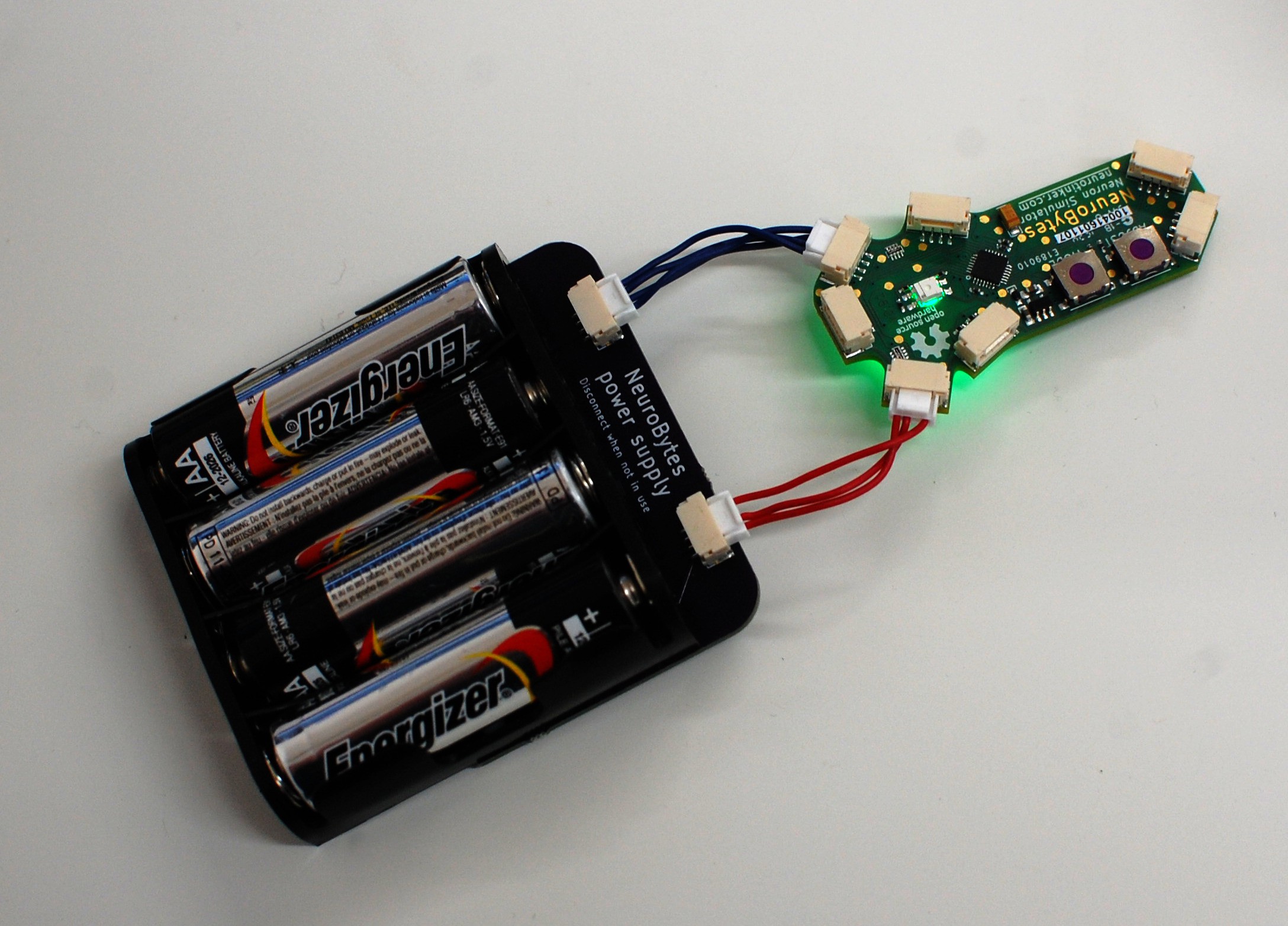
Next steps? Probably one more iteration; I may extend the circuit board a bit to allow more silkscreen documentation (beyond our logo which I like showing off at every possible opportunity). I need to fix a few minor dimensional issues as well, including hole sizes and general alignment. And I'm not convinced the overhang design is the right move; I may keep the board flush with the battery pack and put the connectors on the bottom, along with another pair of bumpers.
Discussions
Become a Hackaday.io Member
Create an account to leave a comment. Already have an account? Log In.
What and where is this resistor divider that is required?
Alarm bells are going off in my head and I want to steer you away from one of the seven deadly electronic sins, if you're doing what I think you might be doing! :)
The AA board looks great, by the way. Fantastic idea, and looks super clean.
Are you sure? yes | no
Thanks!
I'm anxious to learn of this deadly sin--it's certainly not too late for a redesign (ever, with any luck). I switched from using a common 5vdc rail to a 6vdc rail; it gives me a bit more 'oomf' from the servos and simplifies the power supply boards. Also makes the entire system more flexible with respect to neuron-to-neuron voltage drop, since each board regulates down to 5vdc either way.
Unfortunately, my strategy for sending impulses _into_ the network using mechanical switches has always been to simply bridge the VCC rail to one of the inputs. If I do this now, I'll send 6vdc right into the ATtiny which doesn't seem advisable.
So I used a pair of resistors--in this case, a 200-ohm and a 1k-ohm--to form a divider, so when the switch is closed it only sends 5vdc to the dendrite. I've arranged the circuit so the resistors are only pulled in when the switch is closed, if that makes sense. I'll post a schematic if that would make it more clear.
Thoughts? Is that a reasonable approach, or should I use a voltage regulator on every switch board instead?
Are you sure? yes | no
Sounds good! Resistor dividers are acceptable ways to get signal levels where you want them.
I was worried you were trying to use a divider circuit to power your microcontrollers, which would work only until you tried to scale up, and then it would be a Bad Situation. Sounds like you're regulating properly, though.
Are you sure? yes | no
Excellent.
Although this discussion did cause me to look again at my power supply board schematic, and realize that I did screw something up. The Type pin isn't looped into the divider, so it still sees 6vdc. Oops.
Thanks for the comments.
Are you sure? yes | no
Thanks for posting this...it's very interesting to see the iteration, and what works and doesn't. Too often, we see the finished product, and not the sausage-making behind it.
The other point about the 9V-type snaps is that it's trivially easy to momentarily connect the battery (correct pack or 9V) backwards. You probably always need reverse protection, anyway, but it's more difficult to put in all four AA's the wrong way (I've managed it on occasion).
Are you sure? yes | no