 zakqwy
-
Neuron Development: v0.1, the Sketchup plugin
11/10/2014 at 20:31 • 0 commentsNote from Zach: Andrew wrote this up in early April of 2014. I've pasted it here without modification.
Zach asked me to write a little about the prehistory of the Neuron project, so here goes.
This Neuron project goes back a few years, to architecture grad school and a brief obsession with the idea of computer-generated architecture. I wrote programs that generated forms based on random walks, fractal games, and genetic iterators, but what I really wanted was to be able to mimic the accidents and discovery of design by writing a program that would iterate process rather than form: instead of always generating form using fractals or through the application of a pattern, I wanted to codify the decision to even use a tool in the first place, or to change the order of operations performed. I could write code that would do something myself and change it myself, but I wanted code that would rewrite itself.
I began casting around for a way to generate randomized algorithms that always worked. The solution as I conceived of it was to simplify everything to binary--to think of functions as nodes and to normalize their inputs and outputs to either 1 or 0, then generate a random directed graph from a bunch of function nodes, creating random loops and sequences of functions.
I'm not sure what led me to start thinking of the nodes as neurons--maybe I saw something like Randall Beer's periplaneta computatrix and recognized its applicability; I also had a friend who was getting a degree in physiology and I probably had a few conversations about biopsychology.
![]()
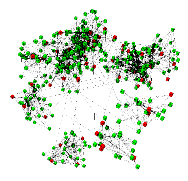
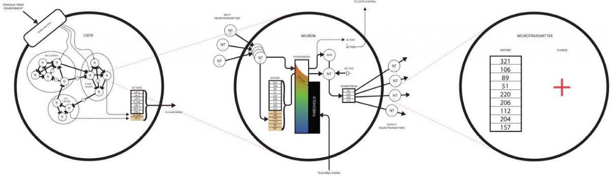
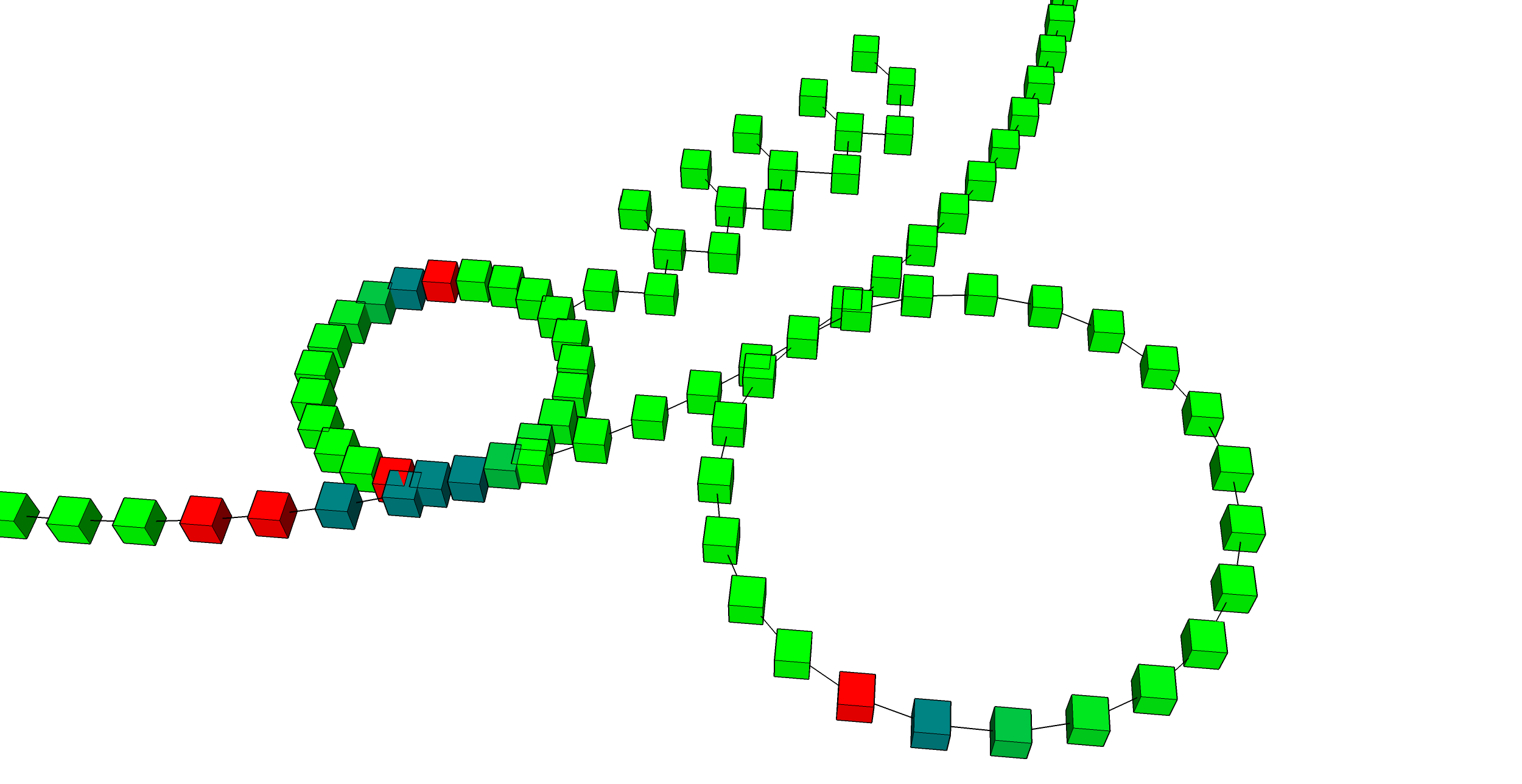
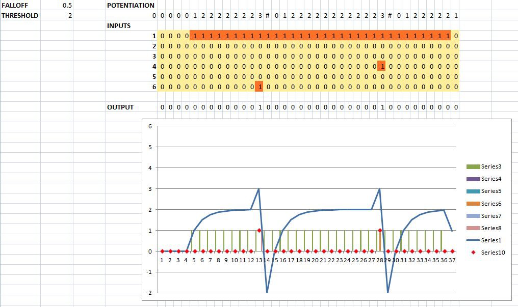
Whatever the motivation, I wrote a program in Ruby using the SketchUp API that would generate a random cloud of 'neurons.' I didn't want the code to execute all at once, and I wanted it to step slowly enough that I could watch it, so I wrote an environment that would keep track of each 'neuron,' its upstream and downstream connections, and the messages it was sending. I then had the environment generate a model of the neurons in the SketchUp environment so that I could see the connections, and I had it color the neurons according to their potential. By allowing the environment to progress one step, every neuron's input was summed, checked against its internal threshold, and if the potential (sum of inputs) was greater than the threshold, a message was sent to all neurons downstream.
![]()
Some of the neurons were designated 'actor neurons,' and when activated would move the insertion point or drop geometry into the 3D SketchUp environment. Some neurons were designated 'input neurons,' and would receive messages from the environment.
![]()
![]()
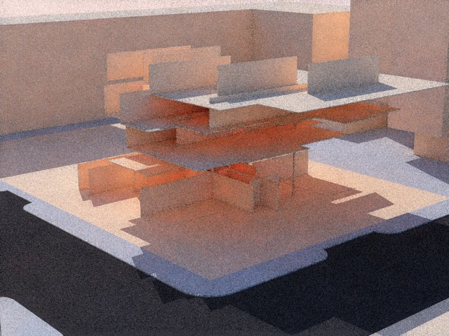
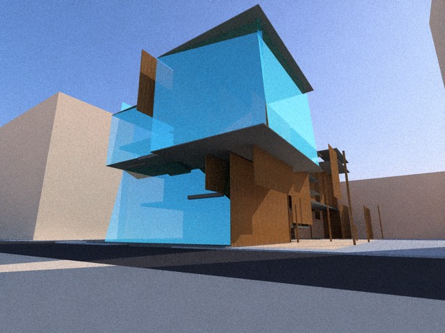
Results were positive--the process certainly generated things, and each generation of randomized algorithm certainly had its own personality.
![]()
The neurons and the networks they created started to be more interesting to me than what they actually produced. I read more about neurons, trying to understand what made them work in our own brains and the brains of animals, and how the model might better mimic organic neurons.
I learned about excitatory and inhibitory inputs, long term potentiation, Rosenblatt's Perceptron, and started to refine the model to be more generalized.
![]()
Early in 2014 I decided I wanted to make physical versions of the software neurons. I knew absolutely nothing about electronics. Zach and I got to talking at a gathering and Zach saw potential in the idea, and proposed we work together.
-
Neurons in five (ish) minutes
11/14/2014 at 00:13 • 0 commentsThis video covers my basic understanding of some highly complex topics, and forms the rough background for what we're trying to simulate.
Comments welcome. More to come!
-
Neuron Development: v0.2, Pro Minis + Neopixels
11/15/2014 at 16:23 • 0 commentsNote from Zach: I wrote this about 7 months ago. Still catching up on background documentation, so I've pasted the post as-is. A bit wordy, I'm afraid... read on if you're bored.
I've been meaning to write this article for some time to document a few generations of Neuron prototypes. For starters, I'll humbly defer to Andrew to cover the original model; while it didn't have an official version number, you can think of it as v0.1. This first proof of concept was a software simulation, a Ruby script that lived in Sketchup and allowed one to seemingly imbue a wireframe model with life. We'll call that Part One of Neuron Development.
I started working on the project after v0.1 was created and improved a few times: tweaking threshold and falloff coefficients, adding a simple GUI, that sort of thing. We quickly decided that the next version would be completely different, present in the physical world with all of its benefits and constraints. Our experience with the Sketchup plugin helped us understand the need for large numbers of devices; while four Neurons could build a basic self-sustaining loop, eight Neurons made the loop more visible. Sixteen Neurons could be linked into two loops of different sizes; impulses would travel quickly around a small loop, dumping new signals into the larger loop until it was finally saturated with noise. Thirty-two Neurons could build an interconnected web whose function was impossible to predict. Larger numbers allowed one to actually visualize "waves" of data sweeping across vastly complicated networks. We found that some complex models produced rapidly building oscillations, while others couldn't keep a signal moving for more than a few seconds.
At that moment, we realized that we needed to scale up production rapidly: not just for cost reduction and packaging improvement, but to demonstrate the truly fascinating potential of the system. Financial optimization was still important, though. Without even considering production scale-up, just building enough prototypes could be cost prohibitive. With that in mind, we decided to intentionally build several generations of devices, hoping to 'iron out' some initial issues while minimizing iterations and design time in the interest of personal engagement.
v0.2: the first physical Neuron prototype
Our main concern with v0.2 was building enough devices to sustain a loop. Without getting into too much detail--that's for another post that dives into potential levels and such--it's important to know that Neurons can only send signals so fast before recovering for a set period of time. The relationship between the recovery time and the signal propagation rate through a network tells you how many Neurons you need to build a loop that never ends: that is, a pulse that starts moving will continue exciting downstream Neurons and moving around the loop, even upon returning to the originator of the first signal. However, optimizing just for those two values will create a scenario so granular it is difficult to discern signal direction; two Neurons, even sending signals unidirectionally via different physical channels, would appear to alternate. Because of this, and to improve the general look of the system, we decided to construct five devices.
The original Sketchup program used colors to indicate internal potential levels of Neurons: green for ground state, turning red as potential increases, then flashing to blue during the recovery period when the internal level is negative. Using these colors produces an interface simple enough to be interpreted en masse: glancing at a network would tell you activity level and make it easy to identify unintentional loops and epileptic conditions. I'd previously worked with RGB pixels of various sorts; once you had the libraries working right, it was pretty easy to modulate colors and intensities to represent complex conditions. I picked up a handful of Adafruit's breadboard-ready Neopixels; I figured they'd have good libraries that would make them easy to integrate, and they were pretty much plug-and-play. For controllers, we got a set of Sparkfun's Arduino Pro Mini 5vdc boards: pretty much the cheapest official Arduino board we could find, and we figured we could repurpose them for other projects at a later point. These aren't natively USB-capable, so we picked up an FDTI cable too for burning new programs.
We knew this first version would be confined to a breadboard; we could have soldered short jumpers directly to the Pro Mini boards and skipped header altogether, but we didn't want to waste a bunch of Arduinos on a potentially failed design. Once the parts arrived, we soldered on header and crammed five of the assemblies into my 2-row breadboard. Not much room for anything, but fortunately the discrete components supporting the LEDs and microprocessors are limited: a few pull-down resistors for the inputs and a large electrolytic capacitor on the power rail is about it. I also like to put a PCB-mount switch on my breadboard with a little power LED, so I can quickly shut down circuits when I put something in backwards. In the video below, one switch excites the Neuron directly to its right, while the other switch excites all five. They're also connected to each other in a counter-clockwise loop:
I'm not going to go in depth on firmware here: partially because I'm more of a hardware guy, and partially because the code I originally worked out for those Neurons never quite worked right. Andrew put together a version of the program that performed much more reliably, but we ran in to a few problems along the way:
- Bouncy switches. That is to say, buttons that "ring" a bit after they're pressed. Most pushbuttons--espeically the cheap PCB-mounted ones I picked up at the local surplus shop--don't make contact cleanly when they're pressed, instead oscillating rapidly between open and closed over the course of a few milliseconds. Rather than adding a debounce routine into our code, we solved this problem using a simple RC circuit to smooth out the 'low' pulses.
- Variable size. We'd power on a few Neurons and run a test or two, then roughly a minute into the run they'd do weird things. Change color, stop responding, or (more frequently) just turn off. We were using unsigned 8-bit integers to measure milliseconds, and once we got to exactly 65.536s (i.e. 2E8 ms), those variables would overflow and weird things would happen to the loops and routines that depended on them. Bumped up to doubles, which are 16-bit integers capable of counting for quite a few more milliseconds.
- Timing. This would prove to be the ultimate downfall of v0.2: the LEDs, while beautiful and easy to use, were extremely processor intensive. Neopixels are WS2812 LED chips mounted on various types of boards, and the WS2812 is a unique beast: it's actually a tiny white circuit board potted in an epoxy lens, containing an RGB LED chip and a dedicated (tiny) microprocessor. In order to render various colors, you just send that microprocessor 8-bit serial data: it uses an internal PWM module to vary the brightness of the three LED elements as needed based on the data it receives. Trouble is, they're really optimized for larger displays of 20, 50, or even more devices. Since they all run on the same serial bus, and they're intended for use at 30Hz update rates for displays, that serial protocol is fast. As in, 800 kHz timebase fast! That may not seem like much, but the Arduino's ATmega chip runs at 20 MHz... and we were running enough code beyond the NeoPixel firmware that we couldn't get a reliable data connection going to the LED. I think it's a problem that we ultimately could have solved given enough work (probably through better use of interrupts and generally more efficient code), but we decided to move on.
Now that I've made it this far, I think I'll split off the next generation into a separate post. v0.3 goes after the problems listed above, and discovers some new ones along the way.
-
Neuron Development: v0.3, many small improvements
11/23/2014 at 19:39 • 0 commentsMore background from this past Spring.
The next phase of Neuron development was a bit faster. In terms of hardware, it was more of a 'tock' compared to the 'tick' of Neuron v0.2. Having said that, we still made a few physical changes to our setup, in ascending order of importance:
- We purchased and assembled 5 additional Arduino Pro Mini 5vdc modules from Sparkfun. While we did consider moving to a different platform, the Arduino gave us tons of power and flexibility (compared to our ultimate plan of a relatively bare-bones processor); also, we already had 5, so it was a cheap way to get 10 Neurons. That means, at the very least, an interesting single loop.
- Andrew got his hands on a monster breadboard; I think it's got 4 rows with a separate power bus. More than enough room to fit ten Neurons with a few support components.
- We ditched the NeoPixels. Personally, I was pretty set on the 'pretty blinkenlights' effect; however, Andrew brought up the excellent point that we needed to get something that worked reliably, and RGB fading LEDs might have to wait for now. Reaching back towards the color scheme of Neuron v0.1, we ended up using a pair of diffused T 1 3/4 LEDs, one red (for trigger indication) and one green (for internal potential level).
Andrew took the lead on the firmware for this generation and we ended up with a much more stable design; without the timing and overflow issues, we were free to build networks and run tests on various neural configurations. Once the basic functionality was validated, we began to experiment with the coefficients developed in v0.1. I learned that the v0.2 program had another issue: the decay time was far too long, at least for building a small self-sustaining loop.
I pulled that video link out of an email Andrew sent my way on Feb 23, 2014. My exact response was:
"Oh man, that is insanely awesome. Man. Man that is exciting. Wow.
We need to make a whole crap ton of these things."
Neuron v0.3 didn't stick around for long; the Pro Minis got re-purposed into various other projects, including a reflow oven controller, a MIDI interface, GimbalBot's test rig, and a few other random projects. But the proof of concept worked well enough; we could definitely see the potential for awesomeness with v0.3.
Time to scale up production.
-
Neuron Development: v0.4 part 1: Goals
11/25/2014 at 13:07 • 0 commentsHigh-level planning for v0.4. I'll dive in to the BOM in detail in a later post.
-
Neuron Development: v0.4 part 2: BOM
11/26/2014 at 01:48 • 0 commentsIn the previous post, I discussed the main constraint of this project--the BOM cost should stay below $5 in reasonable quantity. Between the microcontroller, LED, connectors, and board, that means every cent matters. Before digging into the [quite simple] schematic, I figure a quick overview of the v0.4 bill of materials would be helpful.
Microcontroller
![]()
As mentioned in the video, we're using the ATTiny44A. Digi-Key has 'em at $0.855 each and the chip seems to have everything I need:
- 4K program memory
- 0-20 MHz clock speed (faster than I remembered!)
- 12 I/O lines
- Two timers
Actually, this was something of a crapshoot--I knew how many I/O lines I needed, but I pretty much ball-parked program memory. 4k seemed.. uh.. reasonable.
Programmer
![]() Easy decision--Adafruit's USBtinyISP kit. It's cheap, and [Ladyada] has a great guide that covers using this system in Linux with the free AVR GCC toolchain. This project added 'toolchain' to my vocabulary, so running through her instructions was an excellent learning experience. Technically not part of the BOM, but I needed it for the project.
Easy decision--Adafruit's USBtinyISP kit. It's cheap, and [Ladyada] has a great guide that covers using this system in Linux with the free AVR GCC toolchain. This project added 'toolchain' to my vocabulary, so running through her instructions was an excellent learning experience. Technically not part of the BOM, but I needed it for the project.Connectors
I was shocked by how much board-level connectors cost; I found some awesome Molex surface mount units that seemed perfect, but they were upwards of $0.50 each! I ended using the TE Connectivity HPI platform with 2mm pin spacing:
![]()
2mm pin spacing is a bit funky (2.54mm corresponds to 0.1"), but it keeps the connectors somewhat compact. Remember, I'm trying to cram 7 connectors on each Neuron--6 dendrites and one axon. In any case, the price made the decision easy: $0.02998/connector, $0.0562/header, and $0.01079/crimp terminal.
Crimp tool
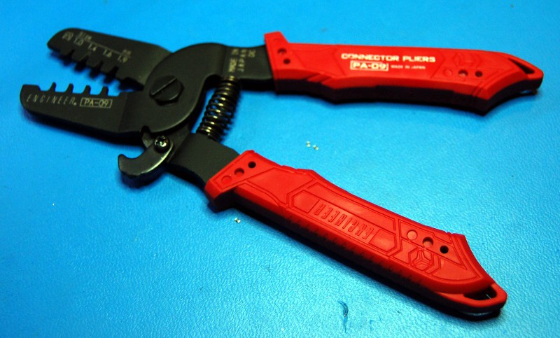
Another tool. The ADS for the crimp connectors recommended a $2000+ press for making connections; the kindly customer service folks at Digi-Key recommended an Engineer PA-09 for $89.95:
![]()
My cousin [Curtis Layton] gave 'em a great review so this was an easy decision to make. If you do the same, I recommend purchasing them on Amazon for half the price :-/
RGB LED
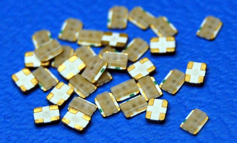
RGB. Small. Cheap. Bright. I didn't give this much thought and ended up with a Lite-On model for $0.279 each:
![]()
What could go wrong? I'll tell you--leadless packages are a PITA to rework without a hot air setup, and 605 nm is NOT red--something I should have remembered from my days puttering about with HeNe lasers.
Other stuff
Very little beyond the board, which I'll cover separately along with the schematic. All inputs are pulled low using 10k external resistors (6 total), and the ATTiny44A has a 0.1 uF filtering cap. The LED has a few dropping resistors since I'm using 5VDC power. Not counting the board itself or any non-board-mounted connectors (or stuff like solder and my time), I'm at roughly $1.50 each if I make a hundred or so. So far so good.
More to come!
-
Neuron Development: v0.4 part 3: Schematic and Board
11/27/2014 at 18:38 • 0 commentsTL;DR: Kicad kicks ass.
I've spent most of my life staring at schematics in one form or another, but everything I've built to this point used some kind of point-to-point breadboard technique. Many years ago I discovered the RadioShack 276-159; it can handle a smallish DIP IC and a few peripherals and is readily available up the street. Great for LM3909s, 555s, 741s, and all manner of random interface boards and LED blinkers.
No good for SMD work, however. For the Neuron, I wanted to go full custom to minimize size and maximize awesomeness. Taking [Chris Gammell's] advice, I took my first plunge into circuit design using Kicad.
Circuit Design
I wanted Neurons to be incredibly simple. As such, they communicate by sending 5VDC pulses to each other--that's it. The interconnections between Neurons--I call them Axons in an attempt to be somewhat biologically accurate--require three conductors, VCC, Gnd, and signal. Taking a cue from servos, I put the VCC conductor in the middle so miswiring would most likely just ground out an input or output rather than short out a whole string of Neurons. As I mentioned in the last post covering the BOM, the only components beyond the seven board-level connectors, microcontroller, and LED are passives needed for signal filtering and current limiting.
![]()
A few notes:
- K1-K7 are 2mm spacing TE Connectivity 3-conductor headers
- C1 and C2 are the two filtering caps recommended in the ATTiny44A datasheet
- R1-R6 are pulldown resistors for the dendrites (inputs)
- R7-R9 are current limiting resistors for the RGB (OGB?) LED
- K8--ah, K8. You'll notice that I didn't include a JTAG header for programming--fortunately, all of the JTAG pins on the ATTiny are shared with various inputs and outputs, so I can program the boards using an adapter harness. All except the Reset pin, so I added a jumper. Simple enough.
Board Design
I wanted to minimize area--not just to save cost, but to make each Neuron as compact as possible. Auto routing is for suckers, so this is what I ended up with:
![]()
Again, notes:
- VCC and Gnd traces are 30 mil--pretty much the largest I could do. Neurons feed power to each other and I wanted to maximize the number per power input; based on some very fast web research, I think that should be good for 1A or more.
- I wish the Axon connector was centered. Oh well. At the least the LED is centered in one dimension.
- Tiny! Well, pretty tiny. I was shooting for <1" on each side but that wasn't in the cards.
- No vias. Vias are for suckers. Or something. That was fairly arbitrary, actually.
- K8, the Reset connector, is just a loop of wire.
- Red is Component Side. Green is Solder Side.
- Cyan is silkscreen on the component side. This was back when I planned for 3 Inhibitory inputs--not the case presently, but more on that later.
- Magenta is silkscreen on the solder side. Neuron v0.4, Salfred Labs.
Salfred Labs
That brings up a great point. What is Salfred Labs, and why is it silkscreened on the Neuron board?
Andrew Salveson + Zach Fredin = Salfred Labs! It's what we thought about calling our company, if we'd made a company. Probably won't happen now, but the legacy lives on in Neuron v0.4.
More to come! Happy turkey day!
-
Neuron Development: v0.4 part 4: Skip the Prototypes!
11/29/2014 at 16:39 • 0 commentsWhen you haven't designed a board before and are planning a decent-sized production run, it's probably a good idea to use a service like OSH Park to test your design prior to scaling up. Silly mistakes are almost inevitable, and squeezing an iteration between Kicad and scale-up is good practice.
Unless you're really impatient, like me.
I ended up working with the kind folks at Gold Phoenix PCB for the Neuron v0.4 boards. A few specifics on the order:
- Everything Neuron is RoHS compliant, since there's a good chance kids will be fiddling around with the bare boards. That means lead-free solder, which means higher temperatures for reflow. As such, I used high-temperature 0.062" FR4 rated for reflow temperatures.
- I included E-testing, fancy light-blue solder mask, white silkscreen, and RoHS-compliant tinning as optional adders.
- I uploaded a single board Gerber and used Gold Phoenix's online tool to panelize and V-score the boards--32 per panel at ~1.2"x1.2" each.
![Neuron v0-4_board1.jpg]()
I ordered 128 pieces; one board came back with a red dot (failed E-test) so Gold Phoenix threw in another sheet--netted me 31 free Neurons, thanks guys! Without expediting, these showed up on my front porch 8 days after uploading the Gerber files. Needless to say, I'm quite happy with how this turned out. $1.9146/piece, and that's before figuring in the free sheet!
After the boards arrived, I frantically hand-soldered one together, crimped up an ISP programming harness, and uploaded a simple program to light the green LED:
![Neuron v0-4_board2.jpg]()
While this didn't tell me everything, at least I can talk to the chip and the LED seems to work. Hand soldering the LED was a PITA, so the next units will be reflowed.
More to come!
-
Toaster oven reflow tangent
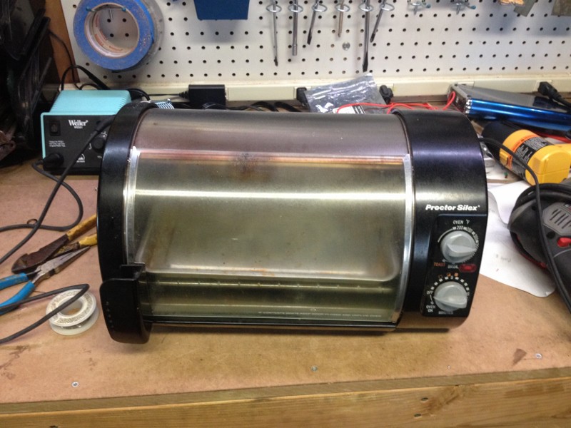
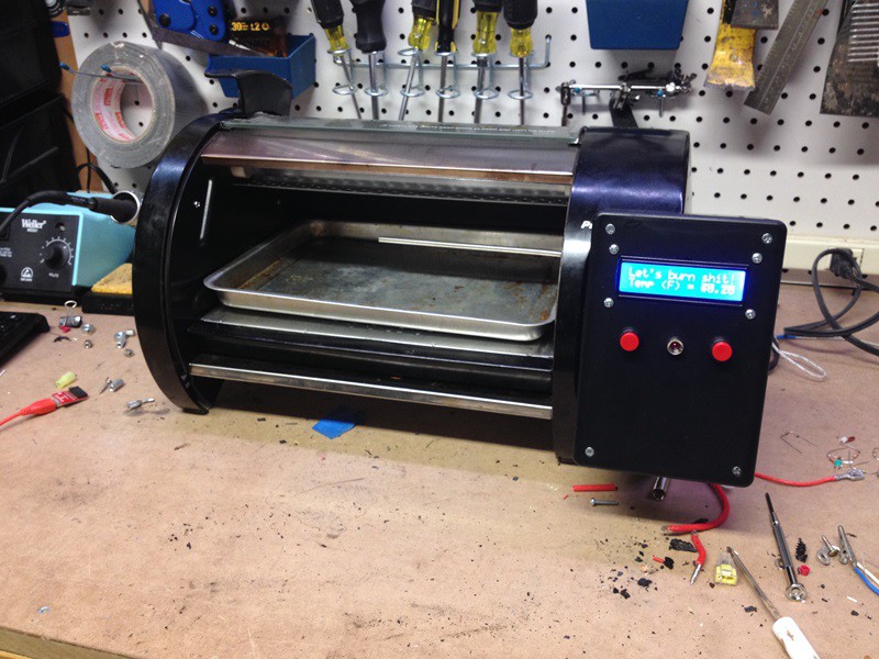
12/03/2014 at 01:06 • 0 commentsMy mom got my wife and I a toaster some time ago; it hasn't seen much use over the last few years, mostly because we don't have the counter space to keep it set up. It's a decent unit--nothing too fancy, no convection system, but it does use quartz elements which heat up quickly. Works well beyond being fairy dirty from use, and it comes with a sweet sliding glass front:
![]()
General plan for the retrofit:
- Ditch the timer and broil/oven controls (that selects between the top and both heating elements)
- Add a large solid state relay, so I can switch the two 600W elements using a microprocessor I/O line
- Design some kind of HMI for starting and stopping the oven, as well as seeing current temperature and program status
- Write a bit of code to follow a predefined temperature 'recipe'
- Figure out how to make the entire assembly robust enough to survive the oven's thermal cycling
This has been done before. Many times. In fact, Rocketscream makes a great reflow oven shield. For folks considering this type of project in the future, an off-the-shelf option like this is terrific. I ended up with something a bit more cobbled together.
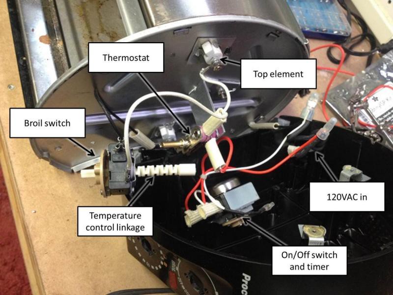
I popped the side panel off to reveal some pretty basic guts:
![]()
Main thing to notice here: everything is designed to survive high temperatures. All of the crimped connectors are insulated using slip-on fiber covers; not seen here are the ceramic supports that insulated the metal screw retainers (one is above the 'On/Off switch and timer' sign) for securing the cover. Additionally, the case itself produced a fine powder when drilled, similar to a phenolic resin; again, likely designed for high temperature exposure. This concerned me a great deal; if the electronics controlling the reflow oven aren't protected from the heat, what stops them from getting reflowed themselves? Even if that doesn't happen, most semiconductors don't like to operate above 180 F or so. Not good.
This seems like a good time to give some general advice on toaster oven retrofit projects: Don't get too fancy. Build a separate box with all of the control circuits and the relay, and have it switch a [carefully labeled] outlet. Then just set the toaster to a high temperature setting, plug it in to your handy box, and you can leave it completely stock beyond the thermocouple installation. As you'll see, I didn't do that.
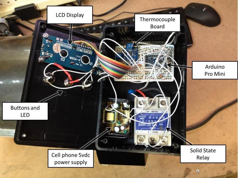
A quick glance through the wiring suggests that the heating elements are both 120VAC, so I cut out the timer assembly and broil switch and wired the quartz tubes in parallel using new crimp rings and scraps of existing fiber insulated wire. I kept the thermostat wired in series with the elements (knob and linkage removed), leaving it set for the highest temperature setting; with luck, if everything goes wrong that will still act as a last-ditch thermal safety switch. Yes, I understand the irony of using the word safe anywhere near this project, but it felt good. On that front, I also installed a 15A/250VAC fuse on the incoming hot AC line, mounted to the plastic enclosure in a handy inline case. Everything else, beyond the thermocouple, ended up mounted in a plastic project box that I bolted to the front of the oven:
![]()
Yup, I already started salvaging Pro Minis from Neurons v0.2 and v0.3. Here it is all buttoned up, with a somewhat profane startup screen:
![]()
A few notes on the design:
- Ended up using a different thermocouple; the stainless steel sheathed unit here doesn't respond quickly enough to air temperature changes (it's really designed for liquid applications). I ended up swapping it for a bare bulb device that came with an old DMM, similar to this.
- The interface is fairly simple; the display shows current temperature, set point, and cycle time. Left button starts, right button stops, and the LED shows when the relay is activating the heating elements.
- The program runs on an extra Arduino Pro Mini we had left over from the Neuron v0.2/v0.3 prototypes; the 16x2 LCD is an inverted version of one of Adafruit's handy boards.
- The box is big enough to hold everything, but just barely; between the protoboard (I didn't make a custom board for this), the HUGE solid state relay, the thermocouple board, the 5vdc power supply for the logic circuits (ripped apart an old cell phone wall wart), and a good bit of display wiring, it's fairly packed.
- I've run it up to >500 F a few times prior to uploading a simple run program. Other than a bit of smoke, everything worked as expected; I suspect that's just excess food, as a subsequent tear-down thankfully didn't reveal any burnt components.
I should have put this disclaimer at the beginning, but if you hadn't figured this out: projects like this are dangerous. I'm confident in my ability to handle line voltage and design this system safely, but I'll still never leave the room with it plugged in (let alone running). Furthermore, I always leave the unit closed and far away from anything flammable while it's cooling down. Also, even though we're using lead-free solder, I'll never use this toaster for food again. If you decide to destroy a handy kitchen appliance, I suggest the same protocols. Don't try this at home!
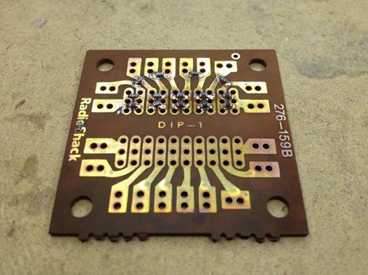
After uploading a rough version of the lead-free solder paste reflow curve, I tried reflowing a few 0603 resisters on a spare RadioShack prototyping board:
![]()
The board clearly isn't made of material designed for reflow temperatures; it started to discolor partway into the process, emitted a horrible smell, and generally stopped looking like a working circuit board. However, the paste reflowed nicely leaving minimal residue, and the resistors all checked out after the operation.
Time to start cranking out Neurons!
-
Neuron Development: v0.4 part 5: Neuron Accessories
12/04/2014 at 03:27 • 0 commentsBefore I cover early reflow oven results, I want to outline a few of the accessories I've fabricated that will help assemble individual Neurons into functional networks. Pretty basic stuff; lots of mindless mass production here. I'm getting better with the Engineer PA-09, especially given that the ribbon cable I'm using is a bit oversized for the connectors (the terminals require a bit of encouragement to snap together).
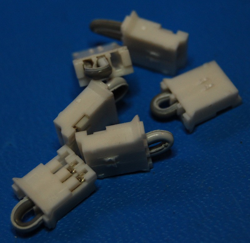
Exciters
![]()
Okay, I couldn't think of a better term for these. Membrane potential modifiers? These are the simplest accessory--just a connector with a loop of wire shorting VCC to Signal. Provided a Neuron is powered through one of the other six ports, these are used to increase (excitatory) or decrease (inhibitory) the resting membrane potential of the device. You'll note I snipped the locking tab off the connectors--I do this with all of plugs to make 'em easier to quickly disconnect. Friction seems to hold them together securely enough for my purposes.
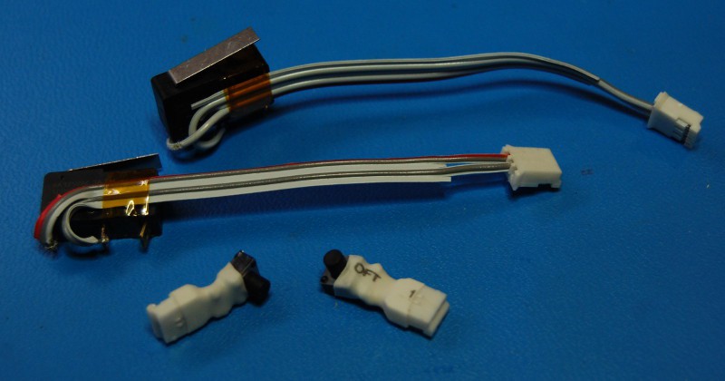
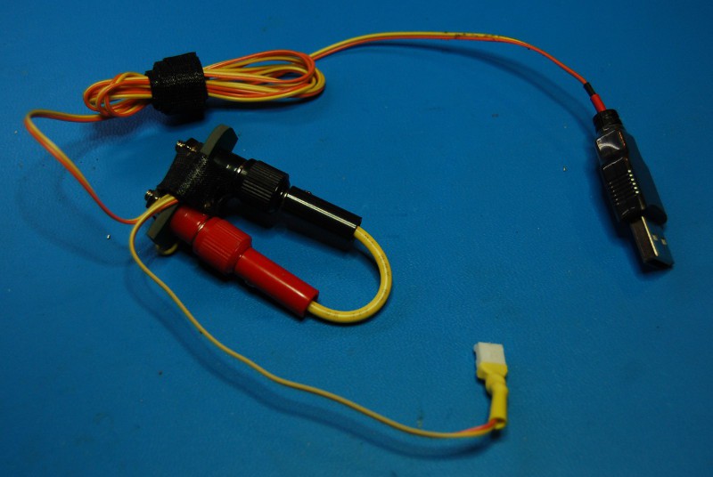
Switches
![]()
Identical to Exciters, but they use a momentary switch to short VCC to Signal. Allows one to locally modify Neuron potential on the fly--ideal for injecting signals and starting cycles. I had a few kinds of switches lying around so I made two types; the snap action version has a ~3" lead, while the tiny pushbutton units are just a bit bigger than Exciters and fit nicely on a crowded Neuron.
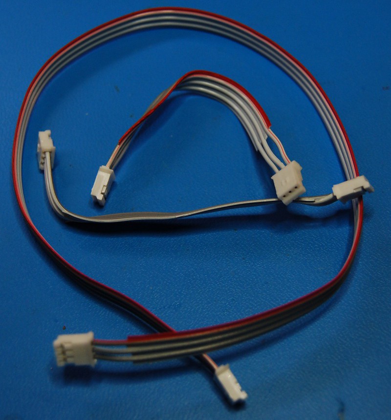
Axons
These are designed to chain Neurons together, carrying both signals and power; as such, they use all three connections (VCC, Signal, Gnd). Various lengths allow for some network flexibility. Fun fact--we made a bunch of these with half of the connectors on backwards, just like a crossover Ethernet cable. That made for some cursing and a few rework sessions. Fortunately, getting Gnd and Signal reversed just makes stuff not work--no magic smoke.![]()
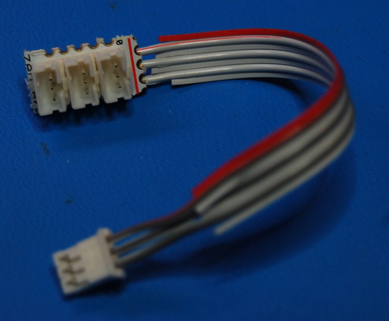
Axon Terminals
![]()
Neurons often link to multiple downstream devices. In an effort to save board real estate, we only equipped each one with a single output connector; these adapters allow one to use Axons to connect to three downstream Neurons. We couldn't do this on the Dendrite (input) side since we wanted to be able to use Exciters; also, I was afraid our software debounce routine would cause us to miss fast sequences of signals. Hence, six inputs.
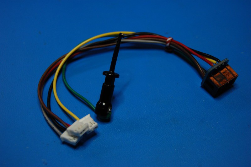
Power Supply
![]()
I made a few versions, some of which hook in to my bench supply. This one is USB powered (I've got a big hub on my bench, along with a bunch of wall warts), made out of an old ribbon cable, and features a current measurement tap. Highly useful.
ISP Adapter
![]()
Covered earlier but deserves another mention here. This is the most important accessory--without it I can't burn Neuron firmware. Built from a few bits of wire, three plugs, a clippy-do (for the Reset loop), and an Adafruit ISP breakout board I had lying around. Generally spends most of its life attached to my USBtinyISP.

 Easy decision--
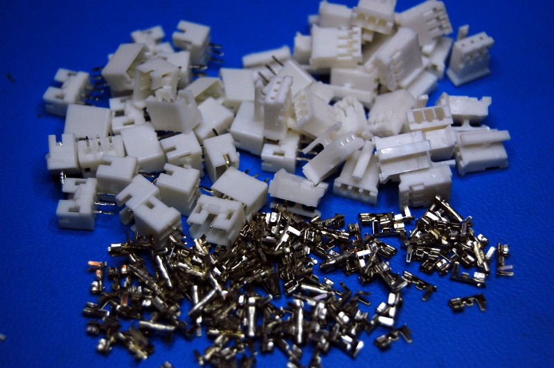


