 icstation
The Chief Engineer of ICStation R&D department Jack is using ICStation UNO R3 compatible with Arduino to successfully make the 74HC595 drive four digital LED display. We will share the schematic diagram, wiring diagram,making steps,download Diagram and also the useful program code designed by ICStation.
When you develop a project, it often needs to make IO expansion.The 74HC595 shifting register is a good choice. Following will introduce you that use two pieces 74HC595 to realize the display system of four digital LED(of course, can also realize 8 digital LED display) .It only uses three IO (PIN2,3, 5) of Arduino.
Components list:
1. ICStation UNO development board $12.69 ( Or Arduino UNO development board)
2.2PCS 74HC595
3.DuPont line: 30PCS
4.four digital LED display with the same anode
5. 20 PCS 20mm pin header
6.Bread board
7.USB Cable
8.4PCS 47Ω resistance
Step 1: Schematic diagram

Step 2: The wiring diagram:

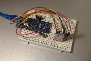
Step 3: To build the circuit according to the schematic diagram

Because we only do testing, maybe it is not practical.If you want it to have practical use, you should weld it manually which will make the circuit more stable. When you build the circuit by hand the pin header is needed which will help you to change the DuPont line to jumper wires immediately.
Step 4: Download Diagram

Step 5: Code for Your Reference

Designed by ICStation
----------------------------------------------------------------------------------------------------------------------------------------------------------------------------------
*/
#define HC_DATA_H digitalWrite(data, HIGH) // data line output high
#define HC_DATA_L digitalWrite(data, LOW) //date line output low
#define HC_RCK_H digitalWrite(rck, HIGH) // rck output high
#define HC_RCK_L digitalWrite(rck, LOW) // rck output low
#define HC_SCK_H digitalWrite(sck, HIGH) // sck output high
#define HC_SCK_L digitalWrite(sck, LOW) // sck output low
unsigned char LED_BCD[16] ={0xc0,0xf9,0xa4,0xb0,0x99,0x92,0x82,0xf8,0x80,0x90,0x88,0x83,0xc6,0xa1,0x86,0x8e }; //common anode digital tube BCD code
//Define the pin
int data =2;
int rck =3;
int sck =5;
// the setup routine runs once when you press reset:
void setup() {
// initialize the digital pin as an output.
pinMode(data, OUTPUT);
pinMode(rck, OUTPUT);
pinMode(sck, OUTPUT);
pinMode(sclr, OUTPUT);
}
// the loop routine runs over and over again forever:
void loop() {
unsigned char dopp =0;
for( unsigned char i=0; i < 4; ++i)
{
if(i ==3) dopp =1;
else dopp =0;
HC_data_analyze(i,i,dopp); //Nixie Tube display
}
}
void HC_data_analyze(char LED_number,unsigned char LED_display,unsigned char LED_dp)
{
// data analyse
unsigned int HC_DISP = 0,HC_LEDCODE,HC_LEDCODE_temp=0;
if(LED_display > 15) LED_display = 0;
HC_LEDCODE = LED_BCD[LED_display] ; //get BCD code
for(unsigned char i=0; i < 8;++i)
{
HC_LEDCODE_temp <<=1;
if(HC_LEDCODE&0x01) HC_LEDCODE_temp |= 0x01;
HC_LEDCODE >>=1;
}
if(LED_dp) HC_LEDCODE_temp &= 0xfe;
HC_DISP = HC_LEDCODE_temp;
switch(LED_number)
{
case 0: HC_DISP |= 0x8000;break;
case 1: HC_DISP |= 0x4000;break;
case 2: HC_DISP |= 0x2000;break;
case 3: HC_DISP |= 0x1000;break;
}
write_74HC595(HC_DISP); //74HC595 shifting register data transfer
}
void write_74HC595( unsigned int data_a) //communication with 74HC595
{
char look =0;
HC_RCK_L; //latch open
HC_SCK_L;
for (;look < 16; ++look)
{
if(data_a&0x0001) {HC_DATA_H;}
else {HC_DATA_L;}
HC_SCK_H;
HC_SCK_L;
data_a >>= 1;
}
HC_RCK_H;
}
------------------------------------------------------------------------------------------------------------------------------------------------------------------------------------
This file is download from ICstation BBS
If you have any question, please visit our BBS:
http://www.icstation.com/forum/
 AndyMac
 Circle Electronic
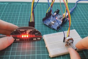
 Yann Guidon / YGDES