 Ethan Durrant
The 8085 microprocessor uses a multiplexed data/address bus to interface with memory. The lower 8 bits of the memory address bus share the same output pins as the 8 bit I/O or data bus, these are meant to be multiplexed using an external Latch IC such as a 74F373 or 74HC573 Octal D-type transparent latch which is enabled by the ALE pin on the microprocessor. Using this method, it writes the upper and lower half of the memory address while the Latch is enabled, then it disables the Latch (but it continues to hold it's I/O states for the address while disabled) and uses the pins for data transfer between the microprocessor and memory until it needs to access a new address. The problem in my situation is that I lack any suitable Latch IC to make this multiplexed bus work, but I have a plan to solve that problem, which is probably the hard way ( but not the hardest ). That plan is to just create the identical latch circuit using 7400 series logic ICs. Sounds simple right? Well it is, somewhat...
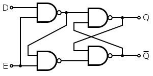
So I start by scrutinizing the datasheets of two Latch ICs that I know work for this situation and trying to figure out how exactly they work. One of those is the 74HC573, which is described as "Octal D-type transparent latch". So I searched for "D-type transparent Latch" and found the description and a logic diagram for it in the Wikipedia article on Flip-Flops.
Here is the image of the logic circuit from Wikipedia that I chose to use, due to the fact that it uses 4 NAND Gates, so I can make it using a single 7400 Quad NAND Gate IC.
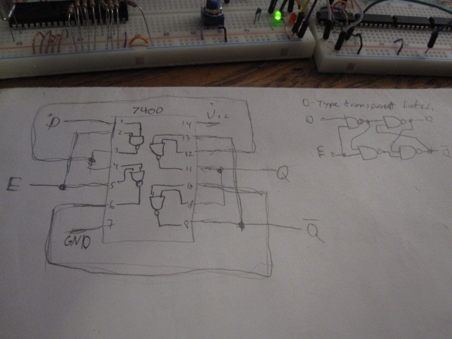
I then took the drew a diagram of a 7400 Quad 2-Input NAND Gate IC on paper and traced out the connections I should make on it in order to create a D-type transparent latch.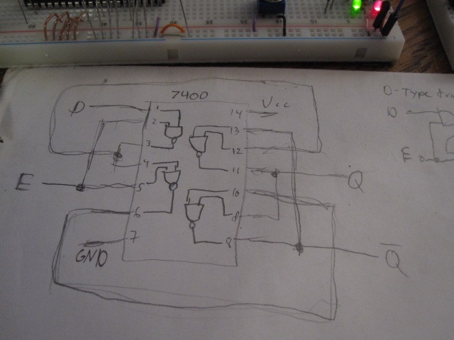
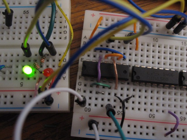
I then proceeded to create the circuit and test it on a breadboard. The Green LED is the Q output, and the red LED is the inverted-Q output, the white wire is the D input, and the green wire is the E or enable input. The Q ouput green LED is ON because the D input is HIGH and the Latch is enabled with the E input HIGH, the inverted-Q output on the red LED is of course OFF because it's the opposite of Q.
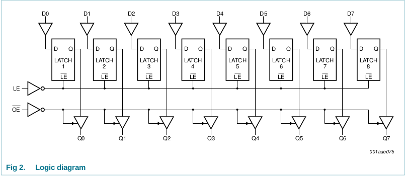
Now that I know that the circuit works, it's time to add the "Octal" part of it by making a total of 8 of these D-Latches as is shown in the 74HC573's datasheet:
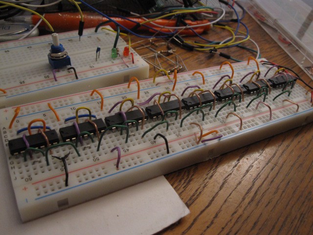
Finally, after stripping many wires, I have the breadboard packed to the brim with 8 74LS00 ICs and completed D-Latch circuits!
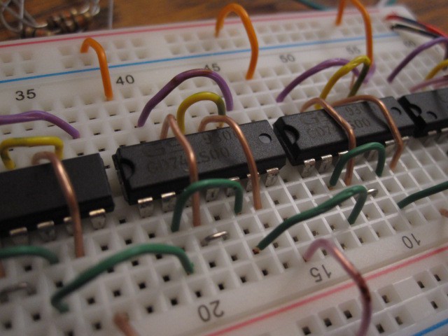
A close-up of the circuits:
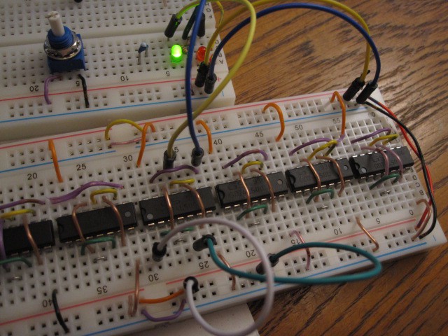
Going through the line, testing each circuit with my 2 LED setup and jumper wires:
Discussions
Become a Hackaday.io Member
Create an account to leave a comment. Already have an account? Log In.