Close
0%
0%

Electromyography Signal Acquisition

Electromyography is the acquisition of action potential signals which characterise the movement of muscles in the body.

Similar projects worth following
Action potentials are spikes of electrical voltage that occur when nerves communicate with tissue in the body. These electrical signals cause muscles to contract, providing us with movement. Variations in the action potential leads to varying amounts of muscular contraction. By observing these action potentials in various locations of the body, information about the movement of muscles can be quantified and converted into digital format for analysis. The acquisition of these signals can come in two main forms, Intramuscular (invasive electrodes) and surface detection. This project focuses on the latter.

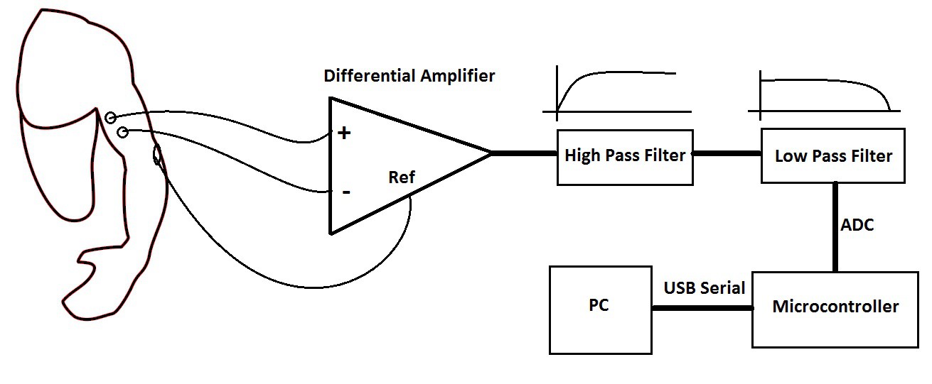
In the first stage of this project, I will focus on a basic circuit which will demonstrate rudimentary signal acquisition with front-end amplification and filtering. In the first stage of the circuit, 3 electrodes are placed on the body, two in close proximity on the medial portion of the bicep and the other on the elbow. The two electrodes on the bicep act as a differential pair, whereby signals common to both electrodes will be greatly reduced at the output of the differential amplifier (depending on the CMRR). This technique removes noise common to both sites, usually consisting of (in Australia) 50 Hz mains hum and possibly noise caused by the electrode-skin interface. The reference electrode is placed somewhere unrelated to the activity of the muscle being studied: The elbow is a good location since it is relatively far from the bicep muscle.

The signal at the first and second bicep electrode can be represented as (s1 + n) and (s2 + n) respectively. At the output of the differential amplifier, we have (ideally)

\color{White} \large (s1 + n) - (s2 + n) = (s1 - s2)

effectively removing the common noise from the signal and leaving behind the difference between the two EMG signals.

After the differential amplifier has subtracted the noise, a high pass filter is implemented with a cut off at 15 Hz. Variations in the electrode skin interface can cause unwanted signals in the 0 - 20 Hz range, so the high pass filter is set to cut out most of these. Next a low pass filter is implemented with a cutoff at 450 Hz which is nearing the higher end of useful signal bandwidth.

The filtered analog signal is then converted to digital via a microcontroller ADC and fed to a PC application like matlab via USB serial for analysis.

References:

Roberto Merletti, Philip Parker, Electromyography: Physiology, Engineering, and Noninvasive Applications, 2004, John Wiley & Sons Inc.

Carlo J. De Luca, SURFACE ELECTROMYOGRAPHY: DETECTION AND RECORDING, 2002, DelSys Inc, Link: https://www.delsys.com/Attachments_pdf/WP_SEMGintro.pdf

  • Signal Acquisition Schematic v1.0

    Jesse01/29/2015 at 13:52 0 comments

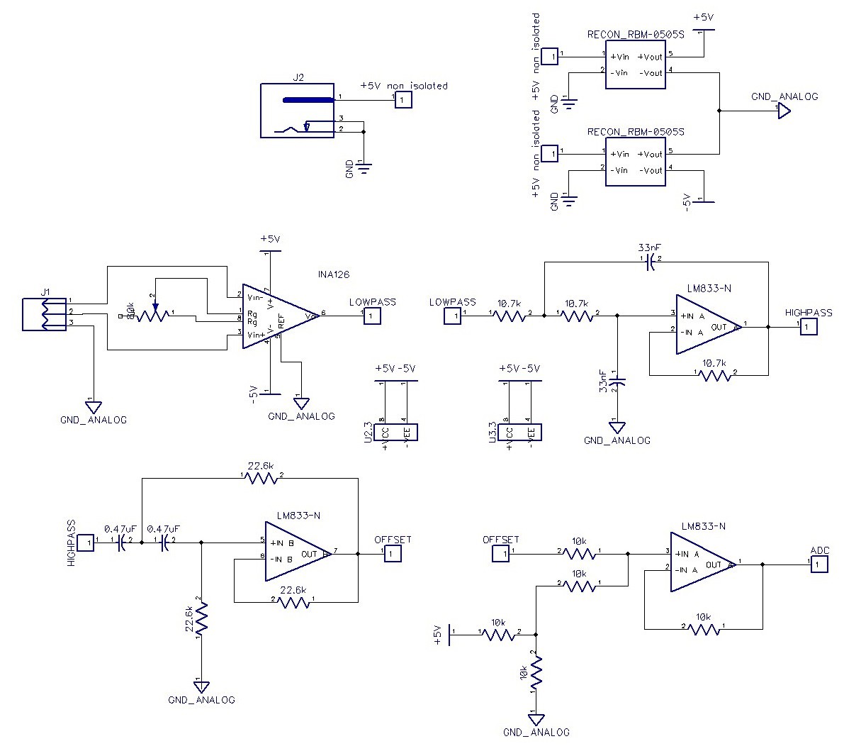
    This circuit consists of 4 stages to acquire the signal from a differential pair electrode. The first stage implements an INA126 instrumentation amplifier that has low noise, offset voltage, quiescent current, input bias current and offset drift. This is a precision amplifier ideal for acquisition of low voltage signals such as those in surface EMG. The potentiometer connected to the Rg terminals controls the gain of the amplifier via the equation

    \color{White} \large G = 5 + \frac{80 k \Omega}{R_{G}}

    The two electrodes on the muscle are fed into the differential input of the amplifier while the reference electrode is used as the ground plane for the signal filtering.

    An important factor that has to be taken into consideration when designing electronics that come into contact with the body is to isolate the power supply circuitry from the signal acquisition circuitry. This is to prevent current flow through the person in the event of a fault and is a requirement of medical 60601-1 design standards. For this project I will implement galvanic isolation through a 3 kVDC isolated DC/DC converter RBM-0505S connected to all the op-amps and in a later stage of the circuit a digital isolator ISO7220xD after the microcontroller.

    In the second stage of the circuit a second order active low pass filter (or Sallen-Key filter) is used with a cutoff frequency of approx. 450 Hz. To calculate the cutoff frequency for a second order RC circuit, the following equation applies:

    \color{White} \large f_{c} = \frac{1}{2\pi\sqrt{R_{1}R_{2}C_{1}C_{2}}}

    Using the values of 10.7 kΩ and 33 nF, the cutoff frequency is 450.7 Hz which is more than close enough for these purposes. In terms of the resistor values, too low of a resistance will require a larger current to create the required voltage drop at the input and too high a resistance will incur non ideal errors due to bias current causing a voltage offset at the output. Resistance values around 10's and 100's of kΩ's are typically implemented in similar circuits and have a satisfactory balance of non-ideal factors, although more will be apparent once the circuit is built. The feedback loop for the amplifier is set to unity gain since amplification is being performed by the INA126.

    The next stage implements a Sallen-Key high pass filter with a cutoff frequency of 15 Hz. Again, resistor values have been chosen in the 10's of kΩ's range and the amplifier is set to unity gain.

    The final stage of signal acquisition is a summing amplifier which offsets the AC EMG signal up 2.5 V so that it is in the 0 - 5 V range. This is purely as a means for making analog to digital conversion easier, there are other ways to go about this issue but this is what I chose to go with for now.

    References:

    Electronics Tutorials

View project log

Enjoy this project?

Share

Discussions

Bruce Land wrote 01/19/2015 at 15:04 point

For safety, you really should isolate the input from mains ground.

  Are you sure? yes | no

Jesse wrote 01/20/2015 at 00:29 point

Thanks for the tip. I haven't got around to showing it yet but I was planning on powering the circuit with a high-isolation dc/dc converter and feeding the signal through an optocoupler.

  Are you sure? yes | no

Similar Projects

Does this project spark your interest?

Become a member to follow this project and never miss any updates