 Adam Gulyas
Bypass capacitors, combined with the input resistance of the next circuit stage, in effect form a high pass filter. This attenuates any frequencies close to DC. Click for more details.
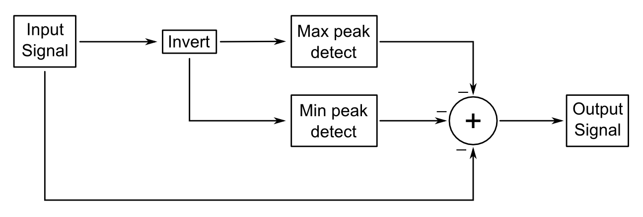
The basic idea of this circuit is to average the maximum and the minimum voltage of a signal and then subtract that average to centre the signal around 0 V. This approach requires a signal with a constant maximum and minimum. For example, an AM radio signal would not work. This approach would be ideal for an FM signal though.
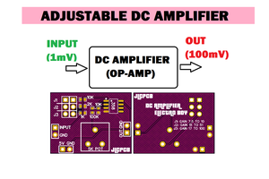
Here's a system block diagram:
Here's a circuit diagram:
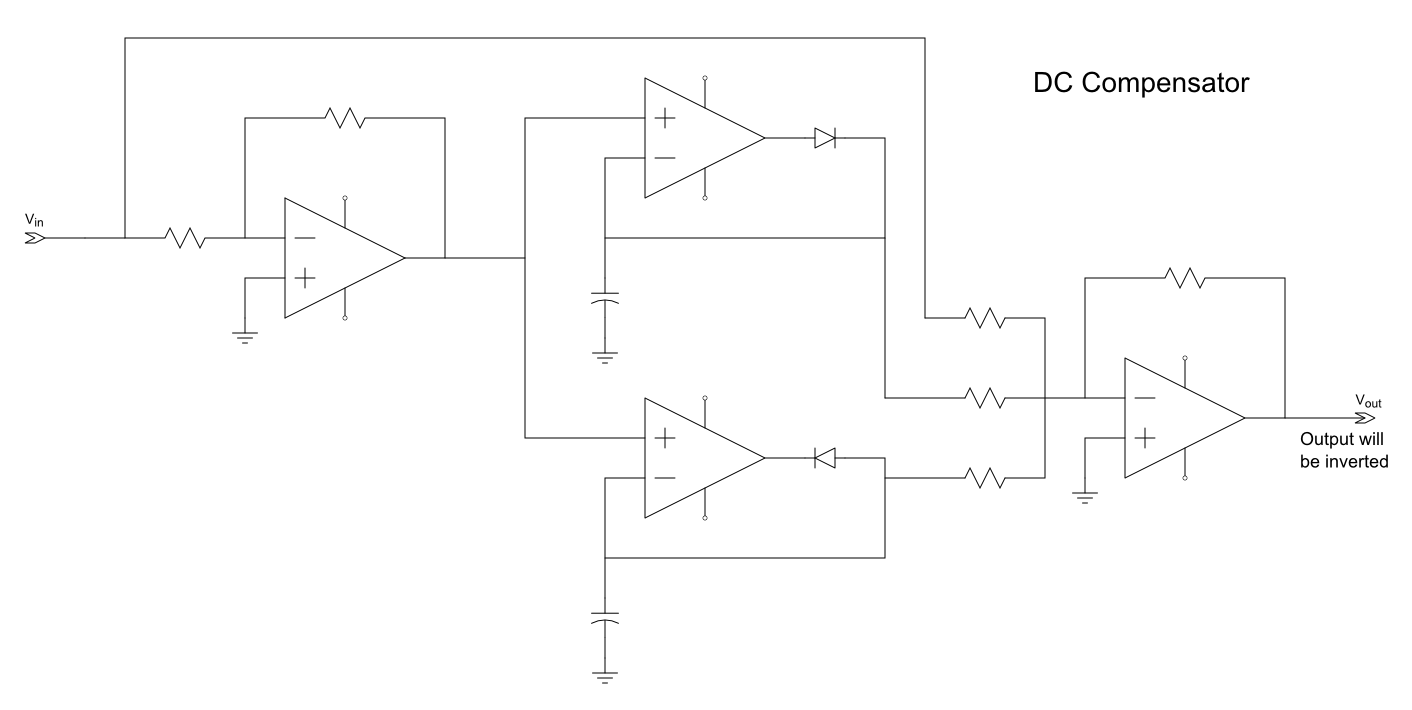
I used an inverter, diode peak detectors, and an inverting summing op amp.
Here's the spice circuit:
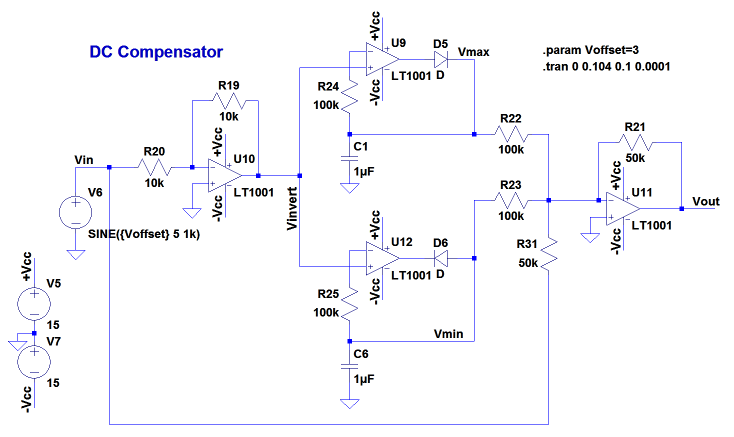
I guess the input impedance of the op amps was not very high since the caps kept on draining. I added the 100k resistors on the inverting input and everything started working.
Of interest is the adding resistor ratios for the summer. I had to double the original signal in relation to Vmax and Vmin. This was because I didn't actually calculate the average of the inputs and outputs, which would have involved more components. (Either a properly scaled voltage divider or an op amp amplifier of gain 0.5.) Also, instead of trying to invert the sum of Vmax and Vmin, I inverted the input signal. This let me buffer the input signal from the peak detectors.
Here's the simulation results:
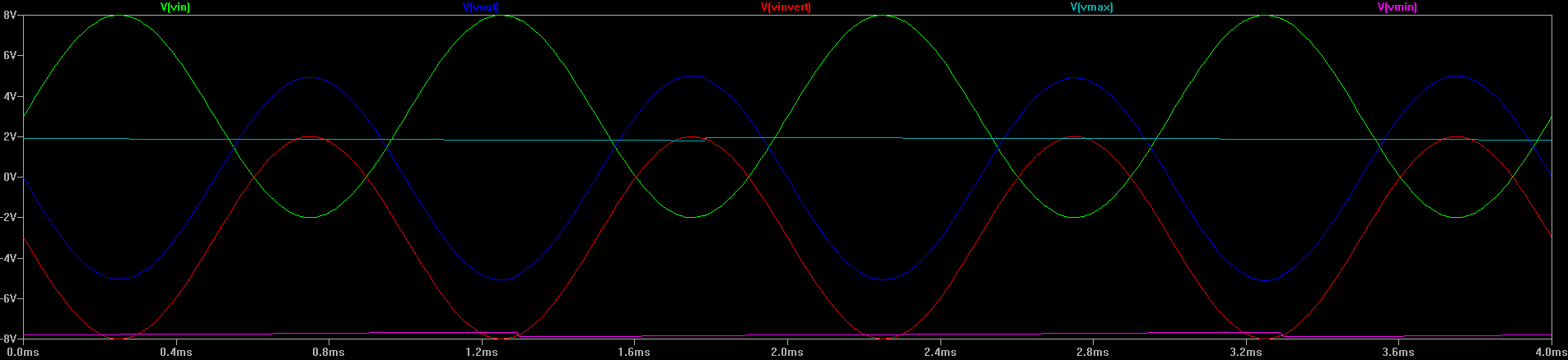
If the image is too small, you can click on the image to the left to see a full sized version. If you haven't used LTSpice before, the graph traces are labelled above the graph, and the circuit nodes are labelled with those names on the schematic.
According to the simulation, the circuit appears to be working. It correctly removed the 3 V DC offset from the input signal (green), although the output (blue) is inverted. For an FM signal this would not matter, but if it's important for your application you could add an op amp inverter onto the output.
At this point I don't intend to take this project further.
 ElectroBoy
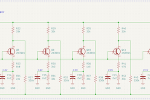
 Manuel Tosone
 MS-BOSS
 Ringo2k