 Kert
KertGot around to thinking through the electronics, cable management and what to do about sensors. For X and Y both home and limit sensors are not a problem, for Z-axis I'll probably go with just a home sensor and skip the bottom limit switch - or use something more conservative with space. Current plan is to use inductive sensors - now plexi is not particularly conductive ;) so I will have to glue a little spacer or nut into the locations where the switches are to trigger them.

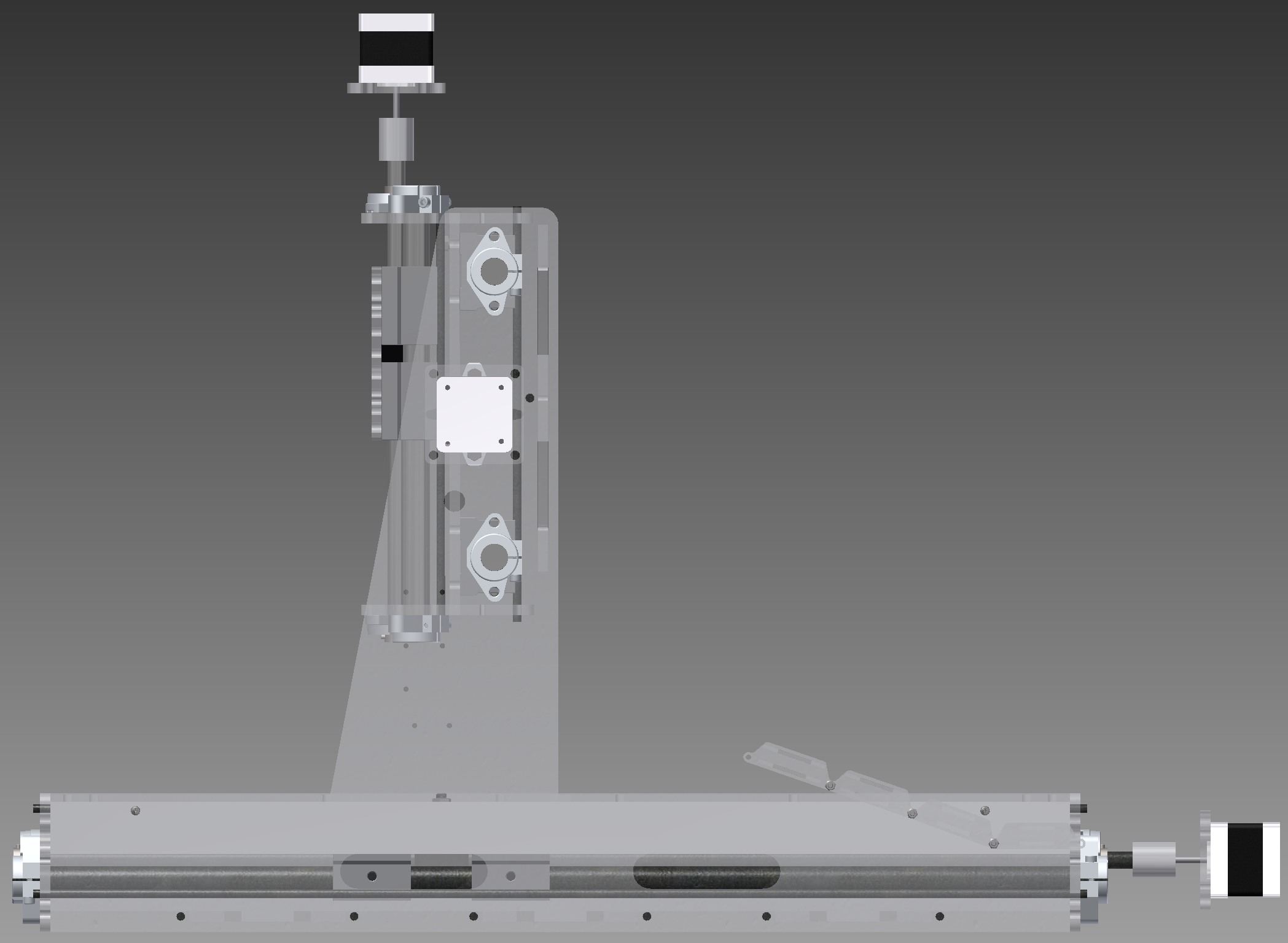
There are now a little extra plates under the stepper motors - just in case, as apparently finding long enough M3 bolts can be quite problematic. The basic idea with cable management is that drivers will be located as close to the motors as reasonable, so I will have to route only power and guidance signals to the moving parts of the machine. I do not know yet the exact dimensions of the electronic components so I have provided small mounting holes for boxes in which electronics will be sitting. For cable chain support the intention is to use 30x30 mm L shaped piece of sufficient legth on one side of machine. Similar solution will be used behind the gantry providing signal to the Z-axis. Optionally a compressed air supply can go also through the cable chain (6mm OD 4mm ID hose, ok for up to 4 bar) although I suspect it would be far easier to just hang it down from somewhere above the machine. The 220V power cable for the Dremel (Actually mine is called Combitool 160) will be hanging from above .. somehow. As I am not all keen on putting that through the cable chain as that way it would be rather hard to remove the tool if needed.

And few more details as well
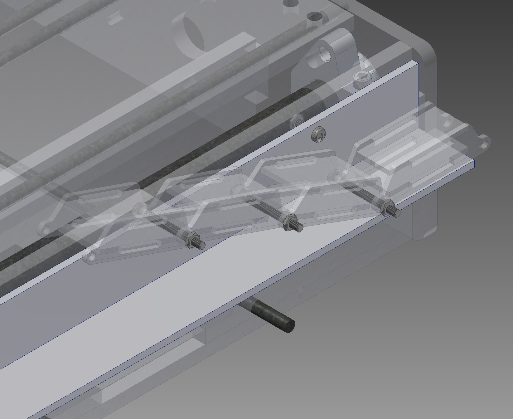
Cable chain. I am still thinking if I will use M3 bolt or a similar size blind rivet for attaching that L shaped profile.
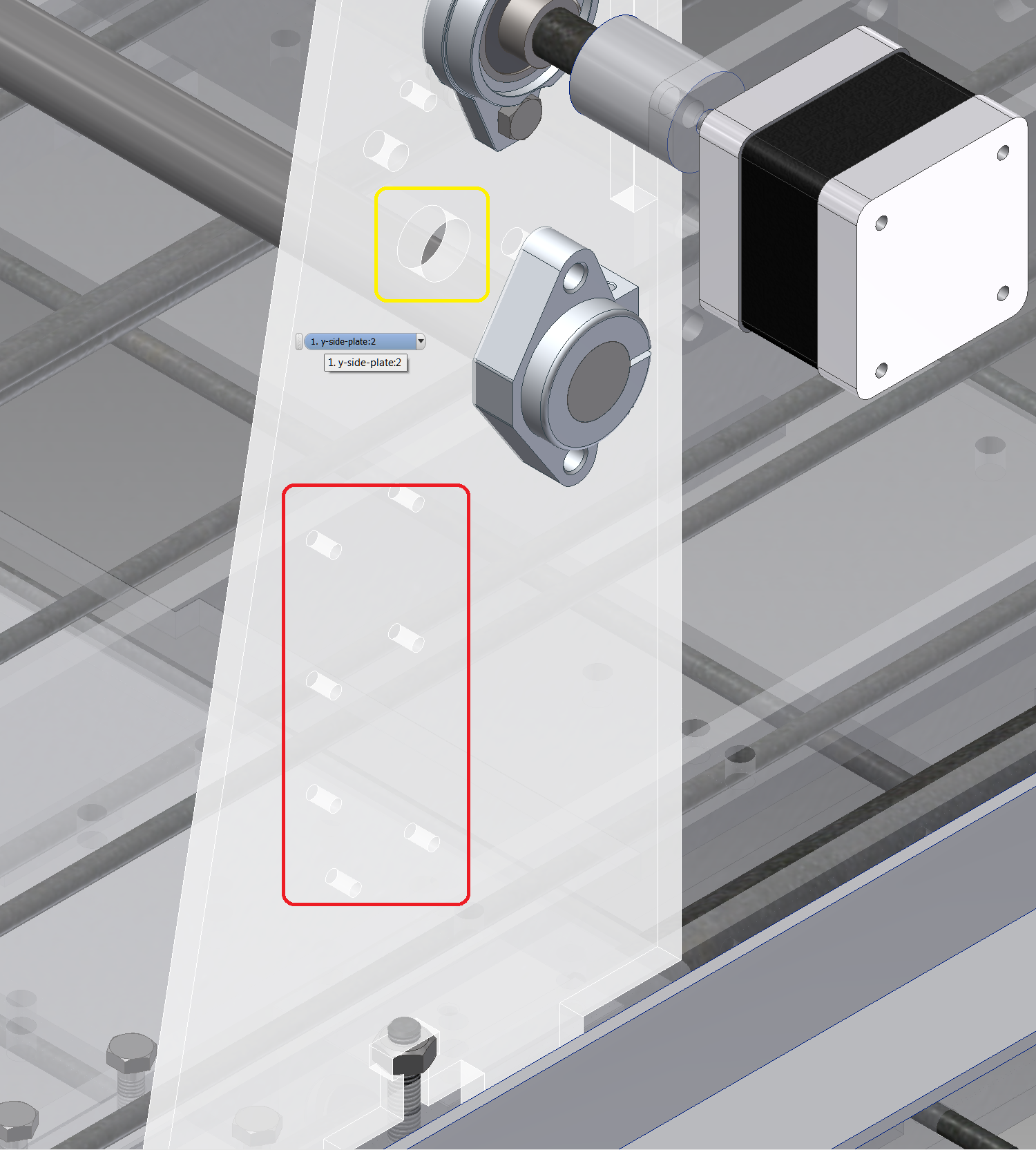
Yellow highlight hole is for inductive sensor and red highlight holes are for putting the box with electronics there. Once the test components arrive and I get around figuring out the exact size of that box.
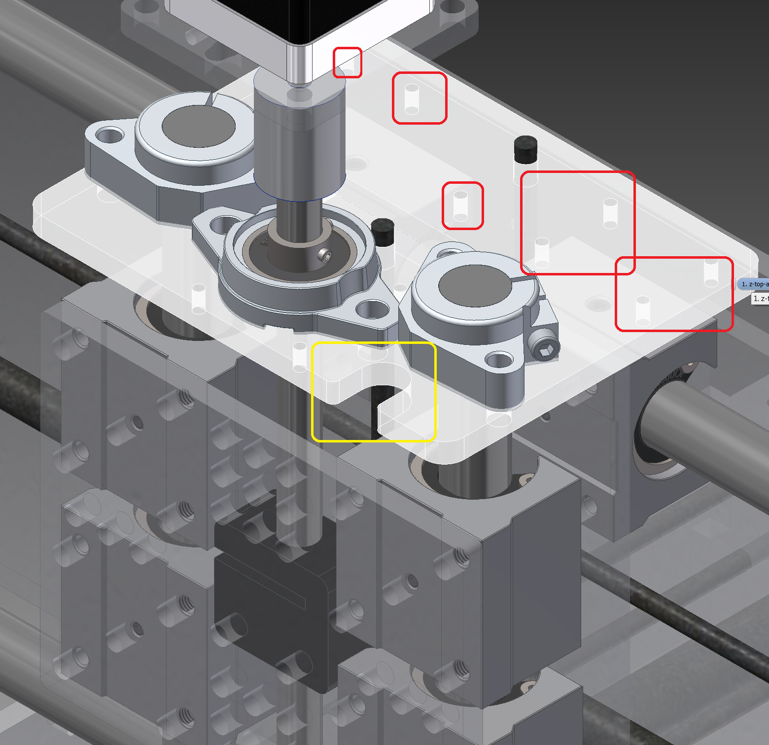
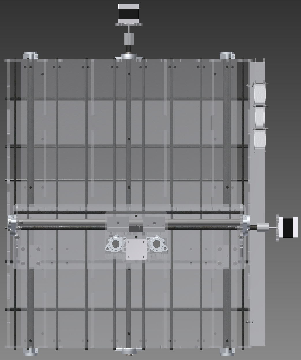
Meaning of colors is the same in this figure as it was in the previous one. Z axis top plate.
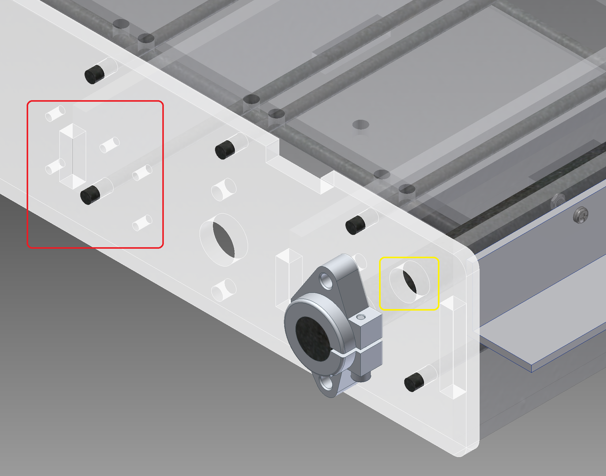
X-axis front plate, meaning of the colors same as above.
So whats next - exporting the component drawings and noting down how many pieces of each will I need, kerf compensation of the components. Nesting them by hand into a 600x400 mm chunks (as I'm not immediately aware of a good nesting program) and then ... then it will be a time to order the materials and after that a cutting time. When the makerlab where I can access the lasers opens in new location early in March.
Discussions
Become a Hackaday.io Member
Create an account to leave a comment. Already have an account? Log In.