 Eric Hertz
This experiment/learning-experience began as my not-so-uncommon accidental-switch to "x-y mode" while trying to zoom in on a brief signal beyond my 'scope's time-scale zoom-ability.
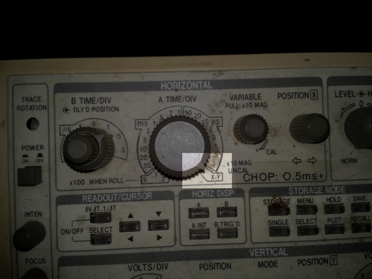
(Obviously, I need to get out the ol' rubbing-alcohol and cotton-swabs!)
I needed to determine the time-delay between the rising/falling-edges of two signals.

Even at maximum-zoom (0.2us/div), these signals appear to be nearly-simultaneous.
I had imagined they should be; these two outputs are two bits on the same port, toggled simultaneously by the same port-write instruction in my microcontroller (an ATmega8515).
e.g.:
while(1)
{
   PORTE = 0x03;
   PORTE = 0x00;
}
The two channels on the oscilloscope are connected to port output pins PE0 and PE1 (bits 0 and 1 on port 'E').After "over-zooming" into X-Y Mode, I saw the following:
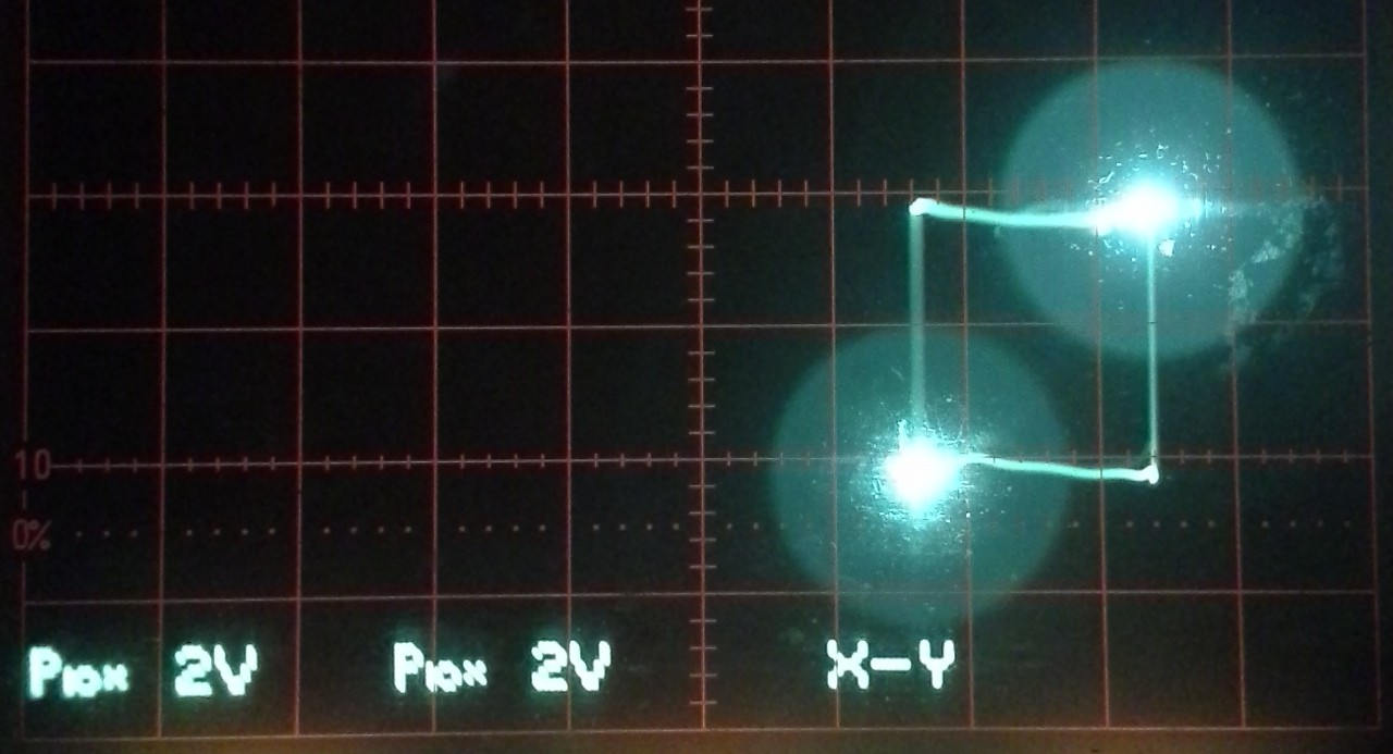
And immediately noticed that *if* the two signals were, in fact, simultaneous, then I should've gotten the two bright dots at the lower-left and upper-right corners, and a straight-ish line between these two points; the graph of y=x (where x is from 0V to 3.6V)... (or maybe a skinny slanted diamond/trapezoid?)
Instead, we're seeing nearly a square.
(NOTE: It just occurred to me that I have two different brands/quality of 'scope probes, which *may* have some bearing on this? The remainder of my discussion will most-likely disregard this new tidbit... until later?)
I also noticed some other characteristics that seem to stand-out:
- [1] The very bright dots at the lower-left and upper-right corners
- [2] The "Square" connecting these two dots
- [3] The "Horizontal" lines appear to be *brighter* than the verticals
- [4] The other corners seem to be significantly "brighter" than the lines, almost a *dot*
- ([5] I didn't notice that the "horizontals" were actually as slanted as they are... this, too, will likely be disregarded early in this discussion...)
It got me to thinking what might *cause* these sorts of effects...?
Before reading-on, know that:
I'm not claiming that my hypotheses--nor even my observations--are *correct*.
As I said before, I've barely ever used the X-Y mode for anything other than some entry-level analog "labs" nearly a decade ago... This is *hypothesizing* and *experimenting*, and some of my observations seem to be corroborated by some loose-interpretation of the data-sheets and maybe a little bit of my experiences with digital-signals/circuitry, and also some (now) glaring-oversights.
For the purposes of this discussion, (at least, early-on) I'm going to assume the signal was *square* and that the 'scope-probes were identical. Thus, meeting the first *four* characteristics, listed above (not the fifth).
Wherein I do some hypothesizing!
The first characteristic is the bright dots at the lower-left and upper-right corners.
These are where both signals are Low (lower-left) and High (upper-right) at the same time.
If this were an ideal digital circuit, with no "rise-time" and no "fall-time", the 'scope would show nothing but these two dots, as all time would be spent either high or low.
//Just Dots:
//
//
//            B
//           *
//
//
//
//   *
//  A
//
//            .       .
//     H      .¯¯¯¯¯¯¯.
// x:  L______.       ._____
//            .       .
//            .       .
//     H      .¯¯¯¯¯¯¯.
// y:  L______.       ._____
//            .       .
//        A   |   B   |  a...
Since digital circuitry is not magical, there must be *some* time between these transitions. Thus, in a slightly-less ideal circuit, I'd expect to see a line connecting these two points. This line might be quite dim, possibly even invisible on a 'scope, if the rise-time and fall-times are very quick in comparison to the time actually spent in the high or low state.
The above idealization assumes that the rise-times of the two outputs are identical, as well as the fall-times (the line: y(t) = x(t)). And, considering that they are from the same port on the same piece of silicon, it seems a reasonable assumption.
//Line:
//(Rise-times needn't be equal to fall-times,
// but rise-times must be equal
// and fall-times must be equal).
//
//            C
//    D      *
//   /     . __
// |/    .    /|
//  ¯¯ .     /
//   *      B
//  A
//
//           .  .       .
//           . /.¯¯¯¯¯¯¯.
//   x: _____./ .       .______
//           .  .       .
//           .  .       .
//           . /.¯¯¯¯¯¯¯.
//   y: _____./ .       .______
//           .  .       .
//       A   |B |  C    |  a...
//                      ^
//                      D
( This is where I verify the above explanation with my 'scope and find that, indeed, my differing 'scope probes, and/or poor calibration, are *largely* to blame. But, continue-on with my hypothesizing, as the corroboratory-evidence was so convincing that I wrote it all up for my own notes before compiling it for the public! It's kinda funny... and still plausibly informative)
The second obvious characteristic is the "square" connecting these points.
If the two dots had a perfect square--no bright-spots at the other corners and no brighter horizontal vs. vertical lines--I'd be led to assume that the outputs were *not* transitioning at the same time. Further, because it's square, it must be assumed that the X rise-time and Y rise-time are *Not Overlapping.*
//Just a square:
//
//      <-E   D
//   .-------@
// F |       | ^
// | |       | |
// v |       | C
//   @-------'
//  A   B->
//
//           .  .       .  .
//           . /.¯¯¯¯¯¯¯.\ .
//   x: _____./ .       . \.______
//           .  .       .  .
//           .  .  .    .  .  .
//           .  . /.¯¯¯¯¯¯¯.\ .
//   y: ________./ .    .  . \.____
//           .  .  .    .  .  .
//       A   |B |C |  D |E |F | a...
(What I *don't* know, is whether the x channel leads the y channel, or lags. I don't think that can be determined in X-Y mode, at these high speeds. The path, then, would be Clock-Wise, rather than Counter-Clock-Wise, as shown.)
The third characteristic is the "other" dots, at the other corners.
These indicate that the two signals are actually at opposite values for a brief duration...
Think about that for a second. That means not only are the two bits output by the same port transitioning at different rates, but also *begin* their transitions at *different times*, despite being *written* in the same CPU cycle. What?! (See later, I'll explain my theory.)
//Square with four dots:
//
//  G   <-F   E
//   *-------@
// H |       | ^
// | |       | |
// v |       | D
//   @-------*
//  A   B->   C
//
//           .  .          .  .
//           . /.¯¯¯¯¯¯¯¯¯¯.\ .
//   x: _____./ .          . \.______
//           .  .          .  .
//           .  .  .  .    .  .  .  .
//           .  .  . /.¯¯¯¯¯¯¯¯¯¯.\ .
//   y: ___________./ .    .  .  . \.____
//           .  .  .  .    .  .  .  .
//       A   |B |C |D | E  |F |G |H | a...
The fourth characteristic is the brighter horizontal lines than vertical.
This suggests that the x channel spends more time transitioning from low-to-high and high-to-low than the y channel (the y channel has shorter rise/fall times than the x channel).
Again, somewhat strange, since they're two bits on the same port on the same slab of silicon. But I've my theories on that, as well...
//Square with four dots and brighter horizontals:
// (This is harder to draw in ASCII-art,
//  thus the y-timing-diagram is shown *squashed* vertically
//  to draw a faster rise-time)
//
//  G   <-F   E
//   *=======@
// H |       | ^
// | |       | |
// v |       | D
//   @=======*
//  A   B->   C
//
//     H     .   .          .   .
//           .  /.¯¯¯¯¯¯¯¯¯¯.\  .
//           . / .          . \ .
//  x: L_____./  .          .  \.______
//           .   .          .   .
//           .   .          .   .
//     H     .   .  . .     .   .    . .
//  y: L____________./.¯¯¯¯¯¯¯¯¯¯¯¯¯¯.\.____
//           .   .  . .     .   .    . .
//       A   | B |C |D|  E  | F | G  |H| a...
//           |<->|  | |     |<->|    | |
//                 >|-|<            >|-|<
//
// NOTE the difference in time spent transitioning in:
//      B and F (horizontal)
//  vs. D and H (vertical)
//  Thus, the 'scope sweeps across B and F over a longer time-period
//  thus appearing brighter.
Thus, I begin hypothesizing:
Forget rise-and-fall times, for a second. The weirdest observation, to me, is the fact that x and y appear to have different steady-state values, albeit briefly.
It would seem there's actually a time, after the simple command PORTE = 0x00; where one bit is high and the other is low. I'm not talking about a difference in rise/fall-time, which could be due to external circuitry. And I'm not talking about "valid" TTL levels, here. I'm talking about a period where each output actually has a different value, or state.
So what could cause this...? Well, there's propagation delays in logic-gates... A brief period where a change in the input signal is not yet (at all?!) apparent on the output. Maybe one output also has an optional output peripheral that travels to the output pin through a multiplexer...? Then that same multiplexer would stand between the PORT register and the output pin... Then there would be a small (gate) delay between the setting of the PORT register and the time that value appears at the output pin... Seems plausible. Further, such a multiplexer may have larger rise/fall times on its outputs than a simple register.
Let's corroborate this hypothesis...
Again, this is my train-of-thought *theorizing*, here. Don't take anything I say here as fact.
I'm working with the ATmega8515.
X, channel 1, is connected to pin 30, PE1 (heh, x is bit 1, y is bit 0).
Y, channel 2, is connected to pin 31, PE0
PE0's optional peripherals: ICP/INT2. All input-peripherals.
ICP is, as I recall, for high-voltage programming. A remnant of the ol' 8051-compatibility days, somewhat specific to this chip... Could require some weird circuitry, but that particular "peripheral" is in fact an input (again, as I recall).
INT2 is *definitely* an input.
Input peripherals shouldn't cause a *propagation delay* on an *output.* They might, plausibly, cause an increase in rise/fall time, due to increased current-draw if they are all tied directly to the input (if they don't go through a common buffer first)... But a common buffer fanning-out to multiple other gates would be easy to implement and would seem likely with the shared-need for other things like Schmitt Triggers, etc..
But who knows about that ICP... that's weird. OTOH, it probably uses diodes, so the load on the input is minimal (micro-amps? nA? pA?) until the programming-voltage is reached.
PE1's optional peripherals: ALE. An output-peripheral.
That's it. PE1, on X, is the channel which appears to be outputting more slowly.
ALE is used for driving a latch, when connecting an external memory-device, *definitely* an output. Most-likely multiplexed with the output of the PORTE-bit1 register.
There's the multiplexer, there's the gate-propagation-delay. And it's on the channel that would appear to have such a delay.
Further Corroboration:
This experiment was done with a slightly more complicated set-up... Its outputs were not merely toggling between 1 and 0, a lot of unrelated math was done inbetween, several unrelated function-calls. The problem I'm trying to debug seems to be related to these two *not* switching simultaneously (as I've seen, here, in X-Y mode, except the circuit shouldn't be *this* sensitive). And worse, I thought, because *one* channel may be switching *somewhere in code* that I can't seem to locate. If *one* channel was switching, it could account for the brighter horizontal lines. OTOH, I would expect to see overshoot *limited to the horizontal-axis*. Which I don't. All apparent overshoot/ringing appears to wrap into the other axis, which suggests that the other axis switches *nearly immediately* after the first (MUCH too quickly to be the next CPU cycle). So, that seems to corroborate the theory, as well, that the brighter-lines are *not* due to code, but due to differing rise/fall times...
FAULTY CONCLUSIONS:
First: Obviously: I need to rerun this experiment with better-matched/calibrated 'scope probes. That basically nullifies *every* piece of corroborating evidence.
But, worse, even in the hypothetical-realm: Maybe you've noticed: Apparently I've been switching around the rise/fall time corroborations with the propagation-delay corroborations. (Of course, that too, I've only noticed as-of writing this). Yeah, a multiplexer's outputs may have different rise/fall times than a register's. But *I* don't know that (would they be faster or slower?). I *do* know that a *propagation delay* exists within a multiplexer... But wait. A propagation-delay would be visible as....?
I gotta look at that drawing again:
//  G   <-F   E
//   *=======@
// H |       | ^
// | |       | |
// v |       | D
//   @=======*
//  A   B->   C
//
//     H     .   .          .   .
//           .  /.¯¯¯¯¯¯¯¯¯¯.\  .
//           . / .          . \ .
//  x: L_____./  .          .  \.______
//           .   .          .   .
//           .   .          .   .
//     H     .   .  . .     .   .    . .
//  y: L____________./.¯¯¯¯¯¯¯¯¯¯¯¯¯¯.\.____
//           .   .  . .     .   .    . .
//       A   | B |C |D|  E  | F | G  |H| a...
An added propagation-delay on the X channel... would cause a square...So would an added propagation-delay on the Y channel.
The difference would be whether the square is being drawn Clockwise or Counter-Clockwise. Which I don't know.
My whole logical-progression of corroborating-evidence is completely bunk :)
Maybe that 'scope image, along with the things I neglected (like the slope of the horizontal lines, the ringing at the corners, etc.) were paid-attention-to subconsciously, and I'll discover that at least *logically* I was on the right path...
Neglecting, of course, that the 'scope probes/calibration appear to be the largest contributing factor.
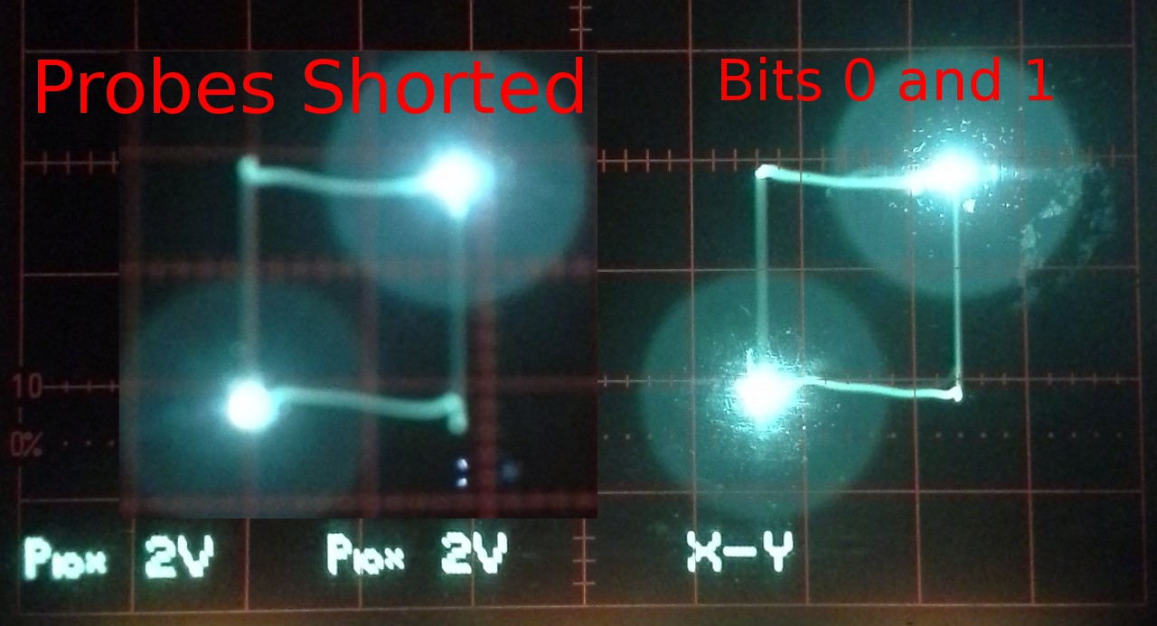
(Probes shorted to one bit, of course)
Fail of the week material? I'd say...
Fail 1: Believing probes
Fail 2: Mismatching evidence
Fail 3: Writing up this damned thing as though I was so sure about what I was saying...
(Hey, someone smarter than me, is at least my analysis of the x-y plot--*if* it were actual bits--correct in the ASCII-art parts?)