agp.cooper
-
Layout update
01/31/2018 at 06:04 • 0 commentsUpdate layout
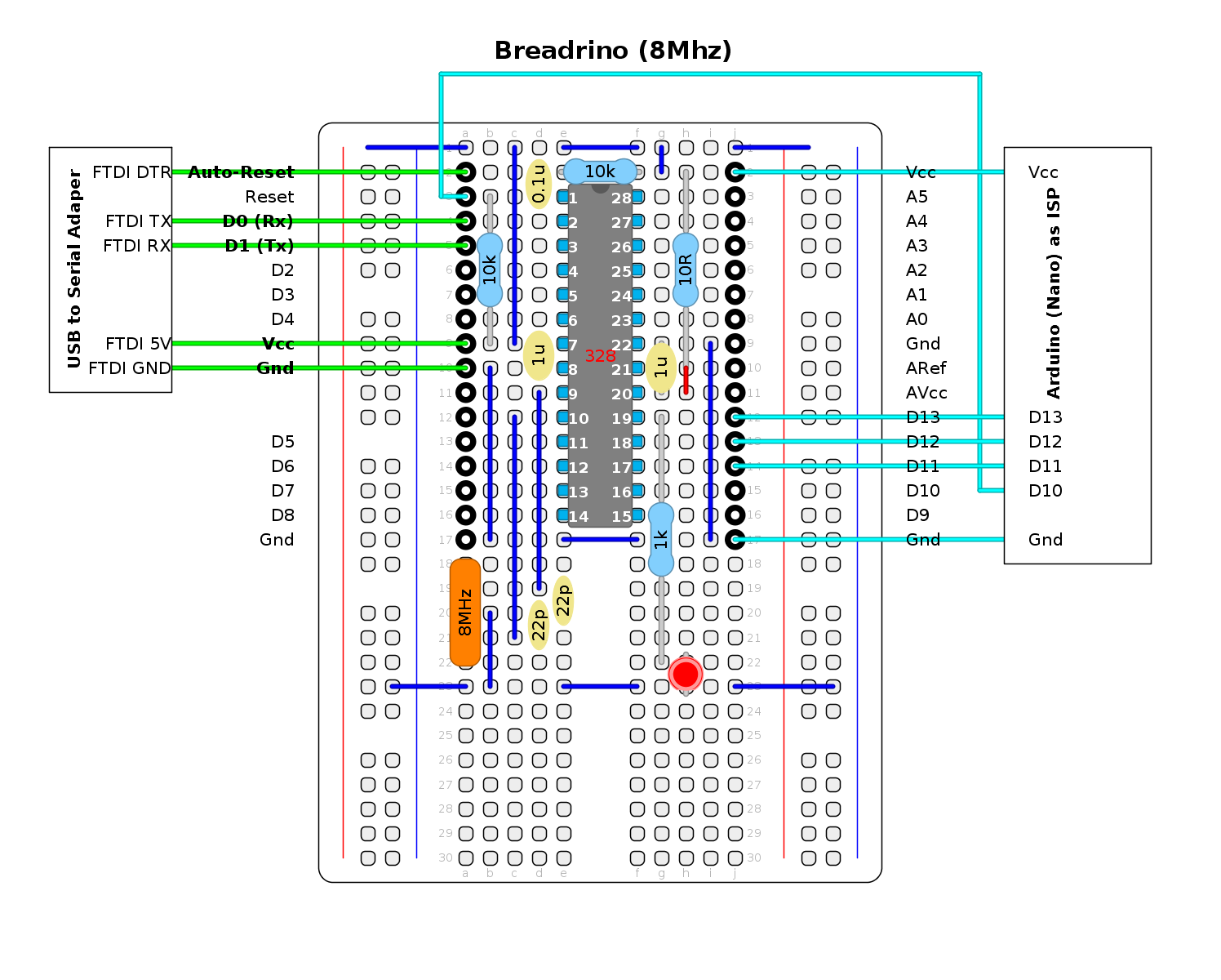
Here is an update of the layout with hookups for the FTDI and the "Arduino (Nano) as IPS":
![]()
The resonator (i.e. crystal and loading capacitor package) has been replaced with a conventional (i.e. larger) crystal. The schematic shows an 8 MHz crystal but a 16 MHz is still okay proving the power supply is 5v.
Note that the 10R resistor now shares a hole with a wire link (red) so that ARef equals AVcc (a previous oversight).
Magic
-
Power Test 2
01/30/2018 at 15:01 • 0 commentsRevisited the Power Test
Spent some time burning the 1 MHz bootloaders I found on the Internet. I was able to burn them but they would not upload a sketch. I could use the Arduino As ISP to upload a sketch but the delay timing was well off. About 16x faster so a general fail for 1 MHz operation.
I had better success for 8 MHz (internal RC clock). Need only a fuse modification to use and external oscillator. Not that surprising that the 8 MHz works as it is the default for 3.3v ATMega328 operation.
Here are the current readings for 5V operation:
- 8 MHz 8.88 mA
- 4 MHz 7.05 mA
- 2 MHz 4.75 mA
- 1 MHz 4.28 mA
- 500 kHz 4.06 mA
- 250 kHz 3.96 mA
- 125 kHz 3.91 mA
- 62.5 kHz 3.89 mA
Here are the current readings for 3.3V operation:
- 8 MHz 3.35 mA
- 4 MHz 2.10 mA
- 2 MHz 1.20 mA
- 1 MHz 0.75 mA
- 500 kHz 0.49 mA
- 250 kHz 0.36 mA
- 125 kHz 0.30 mA
- 62.5 kHz 0.27 mA
Magic
-
Power Consumption
01/29/2018 at 00:34 • 2 commentsPower Consumption
While searching the Internet for the auto-reboot solution, I came across a lot of low power Arduino projects. Given "coin battery" projects are the favour of the month, I though I would test the power consumption of the breadrino using the clock divide settiling.
Here is the test code:
/* Clock divide power consumption test */
void setup() {
  pinMode(LED_BUILTIN, OUTPUT);
}

void loop() {
  int i;

  // Signal start of loop
  cli();
  CLKPR=0x80;
  CLKPR=0;
  sei();
  digitalWrite(LED_BUILTIN,HIGH);
  delay(1000);
  digitalWrite(LED_BUILTIN,LOW);

  // Loop through Clock divides (1/1 to 1/256)
  for (i=0;i<=7;i++) {
    cli();
    CLKPR=0x80;
    CLKPR=i;
    sei();
    delay(8192>>i); // Enough time for the multimeter to settle
  }
}
Pretty simple, flash the builtin LED to signal the beginning of a loop and then progressively lower the clock speed. Hold the clock spped for about 8 seconds to allow the multimeter to settle.
Here are the results:
- 16 MHz 13.54 mA
- 8 MHz 9.26 mA
- 4 MHz 7.36 mA
- 2 MHz 5.76 mA
- 1 MHz 4.98 mA
- 500 kHz 4.53 mA
- 250 kHz 4.31 mA
- 125 kHz 4.20 mA
It looks like 1 MHz is a sweet spot for low power consumption using a 16 MHz crystal and no other power saving options.
Note: with a commerical Arduino board you probably have a power LED burning 5-10 mA on top of these reading (no wonder some people remove the power LED).
Slowing down the clock has other consequences. Off the top of my head: millis(), delay(), delayMicroseconds(), micros(), Serial, SPI, tone(), servo() etc. and any other timing related code will need to be adjusted. You can always adjust the code by going back to full clock speed for those sections of code.
However, there is generic board information and bootloader hex files available for 1 MHz operation on the Internet. Worth having a look!
Magic
-
Auto-Reboot
01/28/2018 at 23:16 • 0 commentsAdding auto-reboot
After some digging I found out how they auto-reboot the Arduino upon sketch upload.
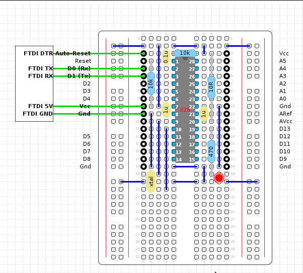
They use the FTDI DTR line via a 0.1uF capacitor to reset the Arduino. Some suggest a 10k pullup on the DTR line is sometimes necessary depending on the FTDI chip.
Here is my updated layout:
![]()
Magic