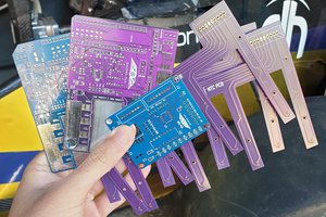
It's been literally ages since I've done electronics from ground up and a number of things have changed since then, not the least reasonable manufacturing of small PCB runs. Since the PCB gerbers are available off the Theremino PMT site, getting started was fairly straightforward. There is a small caveat, though; the published design features a noise-inducing ground loop which the author has helpfully pointed out, but not fixed in the published gerbers.
The advice is to file or cut the trace on the PCB manually, but since I was doing my own run of the boards, I decided to fix that ground loop at the source, on the gerbers. With a little pointers from one of the electronics designers at the company I'm working at, I quickly got the spurious ground loop removed with Eagle PCB (It took a while to realize the schematic and PCB are tied together, so you'll have to make bizarre changes to the schematic), and bill of materials produced for the item. I then sent them to OSHPark, one of the better hobbyist-directed PCB manufacturers.
Here's the first digression of the project, while getting small PCB runs and components at reasonable prices may have gotten easier, in general if you roll your own, you still can't always get components or PCB's one by one. This is generally good, since messing up one PCB for example won't delay your project if you have a spare. However, if you're figuring the cost of building something, the final price will likely be at least triple what you'd calculated from BOM because you order everything in batches (and sometimes extensive shipping costs to double even that final figure). This also means I now have components for at least two more Theremino PMT adapters, though I'm not sure if we're allowed to advertise here :)
While I was waiting for the PCB's to arrive from the foundry, it was time to turn to the component requirements. Okay, I'll confess, I was doing these things in somewhat wrong order. If I'll do something similar again, I will order the components I can get from eBay first, then when most of them have arrived, revise the PCB to accommodate the parts I have and send it in. Then when confirmation of shipping PCB's comes from foundry, I'll set up an order with Mouser or similar for the components I could not source off eBay, "got lost in mail" or won't fit on the PCB layout.
But this time I was over-eager and ordered everything at once. This meant I got the Mouser components within a few days, the PCB's after a few weeks before any eBay sourced components had arrived, and had to wait couple of months for some of the electrolytic capacitors. Luckily, all the eBa sourced components arrived. Getting everything, including the eBay components for which there was often no size specs, to fit on the pre-built PCB took some ingenuity.
For the Theremino PMT adapter, there are several components that can't be sourced off eBay, and some which probably shouldn't be sourced off eBay. The BSP300 Mosfet at the core of the voltage booster I could only find at Mouser, and the 1kV and 1.5kV components, including the RPG02 voltage doubler diodes, belong firmly in the former category that can't be sourced off eBay. I also opted to build the 4 x 1Mohm output stage from 1kV SMD resistors, even if the voltage drop through each one individually is likely to be significantly lower.
The temperature componsation zener diode 1N757A is another Cold War surplus relic and quite expensive, so I decided to substitute it with BZX55B9V1 from Mouser, which side by side appears to have better specs and certainly cheaper if already ordering from Mouser. In retrospect, I should have ordered the 3.3mH boost coil from Mouser as well, but the eBay listing had limited specs that led me to believe it'd be a good option. The eBay one appears to have quite high series resistance, and there was no way to determine which is the inner core lead for higher efficiency.
 aysenurkarga
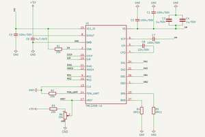
 leo60228
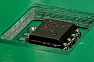
 Benchoff
 Rhys
Rhys