mauswerkz
-
PCB sent off for fab!
05/31/2015 at 01:37 • 0 commentsPut the finishing touches on the layout and silk screen for my inverter control board. This board is the first I've designed using Altium. There were a few things I noticed while laying it out where the behavior of the net-naming didn't work as I expected (a power net that didn't propogate across sheets even though every other power net did, very confusing). Hopefully I didn't miss anything and there are no nasty surprises when it arrives. If all goes well, this should let me get to the real meat of the project: programming. Any other hardware I have to design for it after this should just be simple CAN interfaces and maybe a few light-duty drivers for relays or contactors.
The board is being made by Seeed and should hopefully arrive by the end of next week. Hackaday is giving away "stickvices" this week, which if I won one, would be perfect timing for board assembly. There are more than a handful of 0603 resistors to be placed, along with a few to be put on the other side. Something to hold the board off the bench while I hot-air solder (so the parts on the other side don't get disturbed) would be handy. I've been eyeing the panavises lately, especially at maker faire, but just can't justify spending the minimum of $100 on one, not to mention the suction cup wouldn't work on my bench.
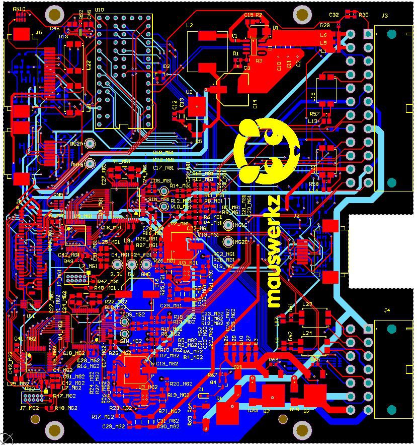
Anyway, here's a picture of the final board layout with the layers in the correct order and silk screen visible:
![]()
-
Inverter control board PCB layout
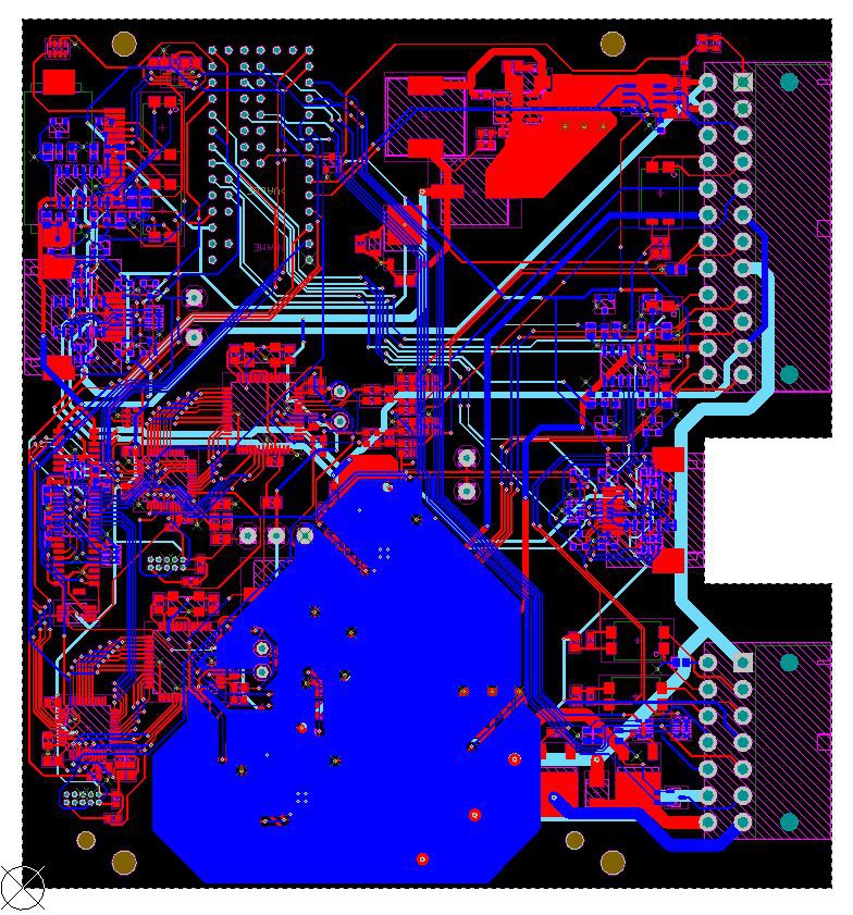
05/28/2015 at 17:01 • 0 commentsGot the PCB layout for my project done yesterday. Before and after images attached. The blue pour is a heatsink for the two high current op amps (one for each motor) I'm using as part of my resolver excitation.
Before:
![]()
After:
![]()
-
200v test run of inverter and transmission
05/25/2015 at 19:09 • 3 commentsOkay, something more exciting to show. I got the charger out of a Chevy Volt working so I quickly hooked it up to my inverter as a power supply to try it out. I set it to its lowest setting (200v). The inverter is still running on the breadboard and Arduino with no current sensing but it does have motor position sensing. If you saw my video from back on the 2nd of this running on 12v, 200v will look a bit more impressive. Again, the final voltage will be 650v.
The LEDs that light up are connected to the oil pressure sensors in the transmission. The input shaft isn't locked yet so it spins with the motor and turns the internal pump. Once the input shaft is locked, I'll have to use the electric oil pump. Interesting fact, the transmission defaults to the high speed gear unless I drive the solenoids to get it do downshift to the low speed gear. This is so that if a solenoid or pump fails at high speed, the transmission won't downshift and overspeed the motor. -
Why the lack of updates?
05/24/2015 at 17:39 • 0 commentsThis project is certainly still progressing! The reason there haven't been updates lately is because the work I've been doing is mostly on the computer for the moment, finalizing the schematics and laying out the PCB for the new inverter control board. Not much to show from that process, but there will be more updates soon. I'm actually taking this whole next week off from work to get the PCB layout finished and sent off to be made. It's a long process that I just won't get done in time if I can only work on it on weekends, so I'll power through it over the next 7 days so I can get back to the good stuff.
-
Examining the Lexus inverter
03/11/2015 at 05:52 • 0 commentsTore in to the Lexus inverter. It has two main sections. There's the inverter section, which has the power electronics for driving the motors (and a really big capacitor encased in aluminum). There's also a "converter" section, which is what boosts the voltage from the original battery (288v) to the high voltage needed to drive the motors (650v). This converter can also step the voltage generated by the motors during braking down to the correct voltage to charge the battery.
For my project, I'll have to figure out how to control the power electronics using my own hardware. This will involve determining the pinouts of all the connectors, where the sensors connect and how to read them, and generally how it all goes together.
DIY Electric Vehicle from Recycled Parts
Converting a car to electric drive using recycled and salvaged EV and hybrid components.