 Blecky
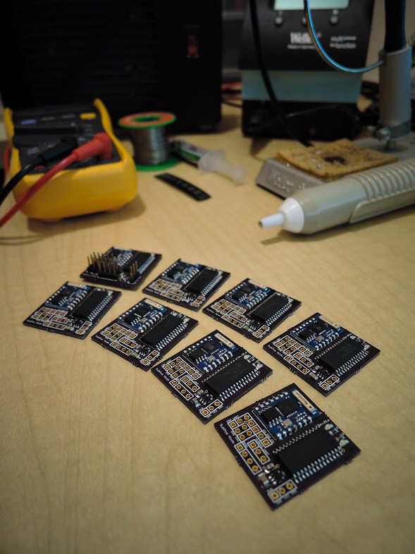
I have finally finished hand soldering all the nodes up:
So where to from here?
I am still making the final feature polishes to the SubPos Node firmware for the PIC (the ESP module firmware for the Node is done). Once that's done I want to get some new performance numbers in controlled conditions and tweak the Android API further.
Having done all that, I will start looking at a revision 2 of the Node PCB as well as a new SubPos receiver device that can use multiple ESP modules for spatial diversity and can be embedded into devices such as drones and the like.
Also stay tuned for a bigger and better demo video shortly.
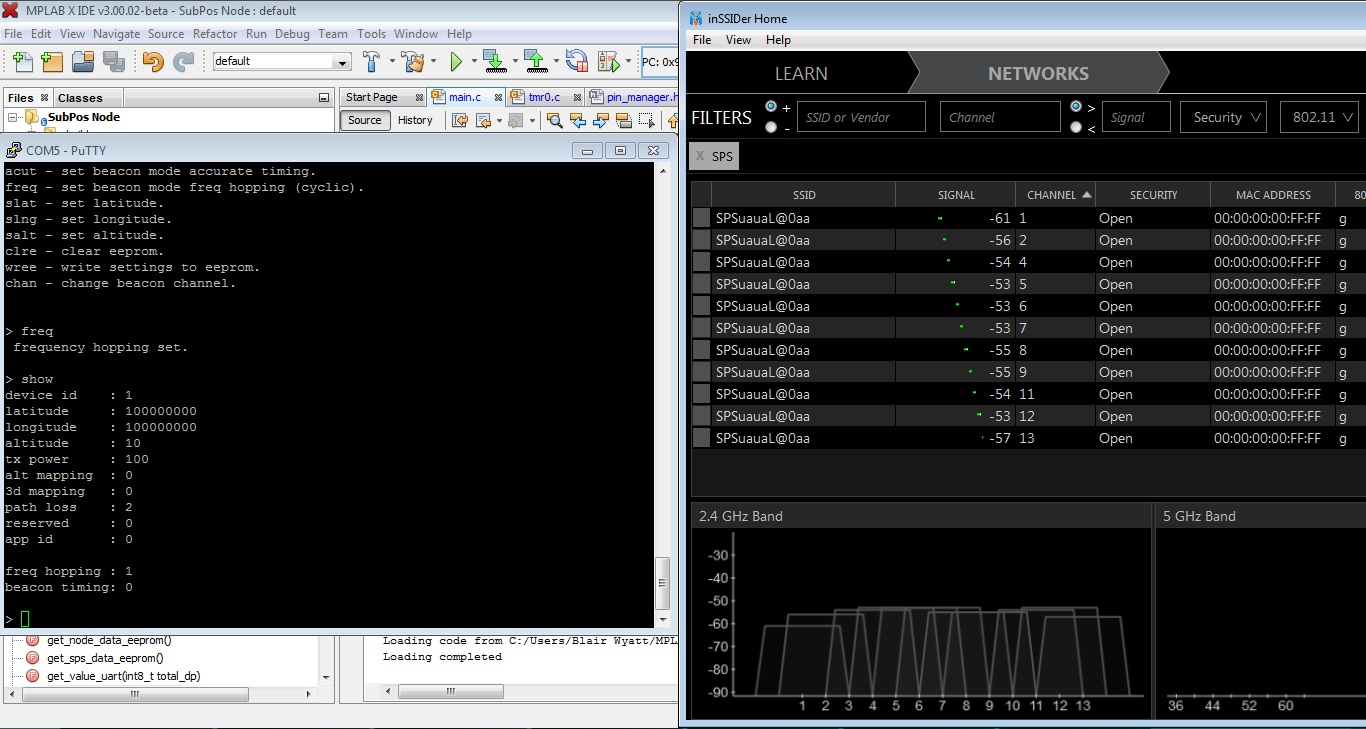
Edit: Frequency hopping now working in the SubPos Node firmware. The firmware is pretty much complete for the moment.
Edit 2: Rolling median and averaging filter now implemented in the Android API. Initial tests seem to be giving much better results on distances.
Edit 3: Nodes programmed, stands built to hold nodes off the ground. Ready to do some testing tomorrow in an underground carpark and gather some data. I will be testing 4 nodes in a square arrangement about 6 meters apart from each other with a receiver at .5m intervals. I will then test 8 nodes in an octagon shape. Each test will be performed with both single channel and frequency hopping.
I will post the raw RSSI data as well as the positional data for anyone interested.
Discussions
Become a Hackaday.io Member
Create an account to leave a comment. Already have an account? Log In.
Ok so with porting all code to esp it is possible to use nodemcu board or make own esp12 board. I have plan to make DHT22 nodes with battery using arduino libs to esp. So I start think that maybe these same nodes can also act as subpos nodes. Naturally it needs work to port native esp code and pic code to one "arduino" project.
Are you sure? yes | no
Definitely, that would be awesome! Be sure to check out the v2 ESP firmware which has some additional functions which also make it more secure by only generating raw beacon frames (https://github.com/subpos/esp_firmware_v2).
The PIC also has a nice config menu which controls the ESP with the AT commands. The menu is shown in this post - https://hackaday.io/project/4872-subpos-positioning-system/log/24113-revision-03-nodes
The pass-through commands just control the ESP module with a transistor switch (https://github.com/subpos/subpos_node/blob/master/Schematic.png) and allow you to flash it via the USB-UART interface, so you shouldn't need to implement those.
If you need any help let me know.
Are you sure? yes | no
Can soneone tell what is point of that PIC? Why that all code does not just run in ESP8266?
Are you sure? yes | no
The main reason for the PIC in the current version is that it provides USB to UART functionality. It controls the power of the ESP module and it can allow you to program or reset it if something goes wrong (watchdog timer).
The other issue is program space. At the time of development it was very difficult to fit the extra code on the ESPs with smaller flash. The original plan was to also create an accurate external timer for beacon frame transmission, but this has been removed.
Are you sure? yes | no