 Benchoff
It's about time to figure out how much aluminum extrusion I should get. Since I'm basing this off the D-Bot, it only makes sense to check out the awesome assembly manual and figure out how much extrusion I should buy:
My bot is going to be much longer, and the original C-Bot has an extrusion length calculator to figure how much extrusion to buy and how to cut it. What I'm doing is heavily modified from either the C-Bot or the D-Bot, so I'll have to make this up as I go along.
The cut guide will be based entirely around the bed. already have the dimensions for the bed - 27cm by 112cm from corner hole to corner hole - so I can just build it out from there.
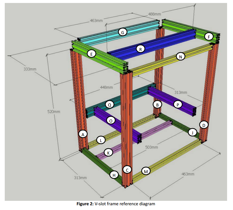
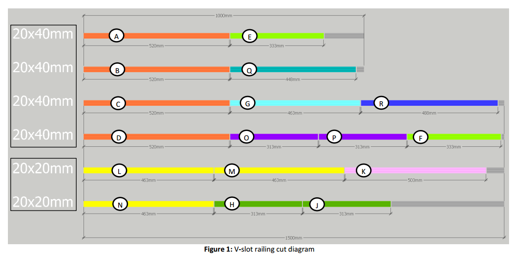
Parts Q, Q', O, and P
Parts Q and Q' (There are two Q pieces) are the main pieces of the Z-carriage. O and P are cross members, joining Q and Q' together. The dimensions for these parts can be derived directly from the size of the bed.
O and P: this cut is simply the distance between two mounting holes in the bed across the Y dimension, plus the offset from two printed bed supports. This offset is 5mm per side, and the distance across the 'short' side of the bed is 27cm. Parts O and P are 280mm long.
For parts Q and Q', we must add the length of the 3x3 corner bracket and half the length of the bed support. The 3x3 corner bracket is 6cm long, and the bed supports 3.5cm long (we can round that up to 4). Therefore, the distance between O and P are 110+(6+2)+(6+2) = 1260mm. Space for the Z-axis leadscrew is given by this graphic, with the z axis mount being 50mm in the relevant dimension:
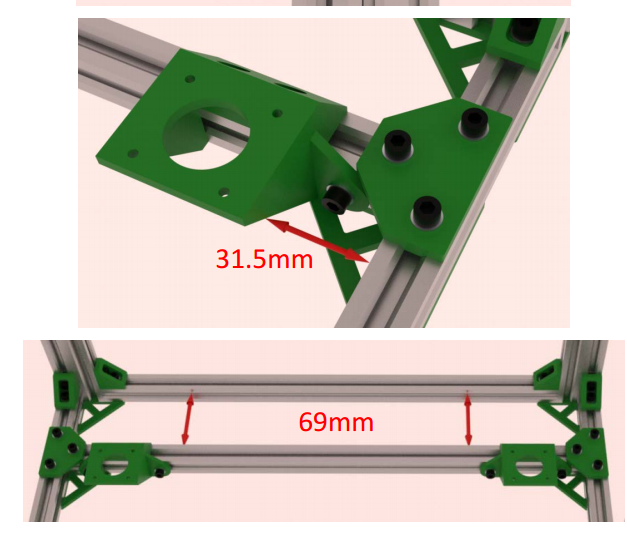
This adds 25mm + 25mm + 20mm +20mm = 90mm to 1260mm, or 1350mm. That's the length of the Z axis carriage.
That's four cuts, netting four pieces.
Part R, the CoreXY carriage
Part R is simply 40mm longer than part Q. That means it's 1390mm long. That's another cut.
Part G, the top back piecs
This part is 15mm longer than part Q. That means it's 1365mm long.
Part E and F, the top short pieces
They're 20mm longer than parts O and P. O and P are 280mm long, meaning Parts E and F are 300mm long.
Parts A, B, C, and D.
These parts determine the Z build height of the machine and are effectively arbitrary. I very much doubt I'll be using a lot of Z height on this printer (and is antithetical to the entire idea of this printer, anyway). Therefore, I'm going to make the sides for this printer square. Why not? If I don't like it, I can just buy another $17 piece of extrusion and make the printer taller.
The front to back depth of this machine is the length of O and P, plus 40mm. These pieces are 280mm long, which means A, B, C, and D are 320mm long. Cut four of them. That's it for the 20x40mm extrusion.
The 20x20 mm extrusion:
Parts L, M, and N:
These parts are the same length as part G. They're 1365mm long
Parts K and K'
There are two K pieces and are 40mm longer than L, M, and N. They're 1405mm long.
Parts H and J
The same as O and P. They're 280mm long.
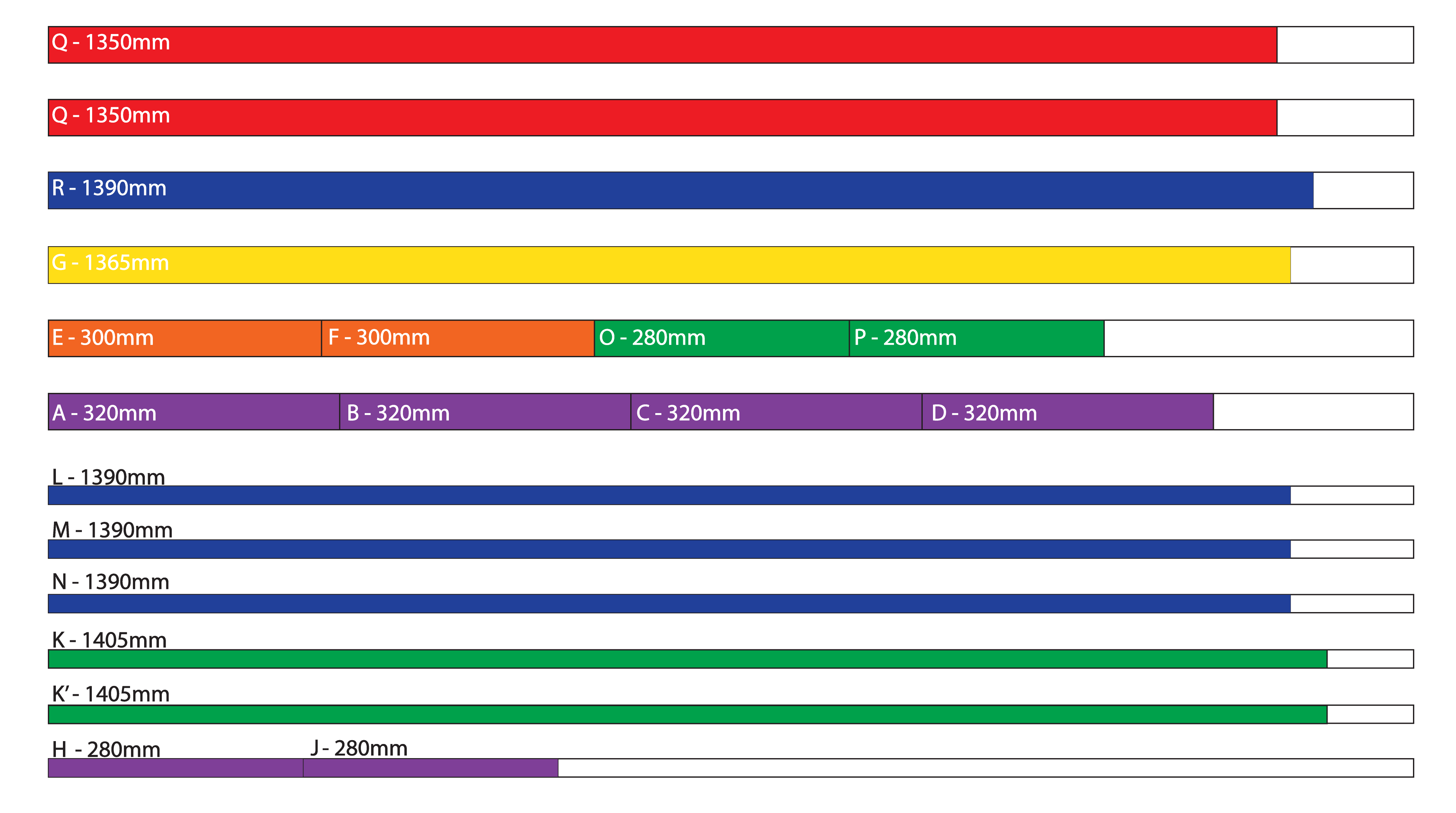
Here we go:
Discussions
Become a Hackaday.io Member
Create an account to leave a comment. Already have an account? Log In.