-
1Step 1
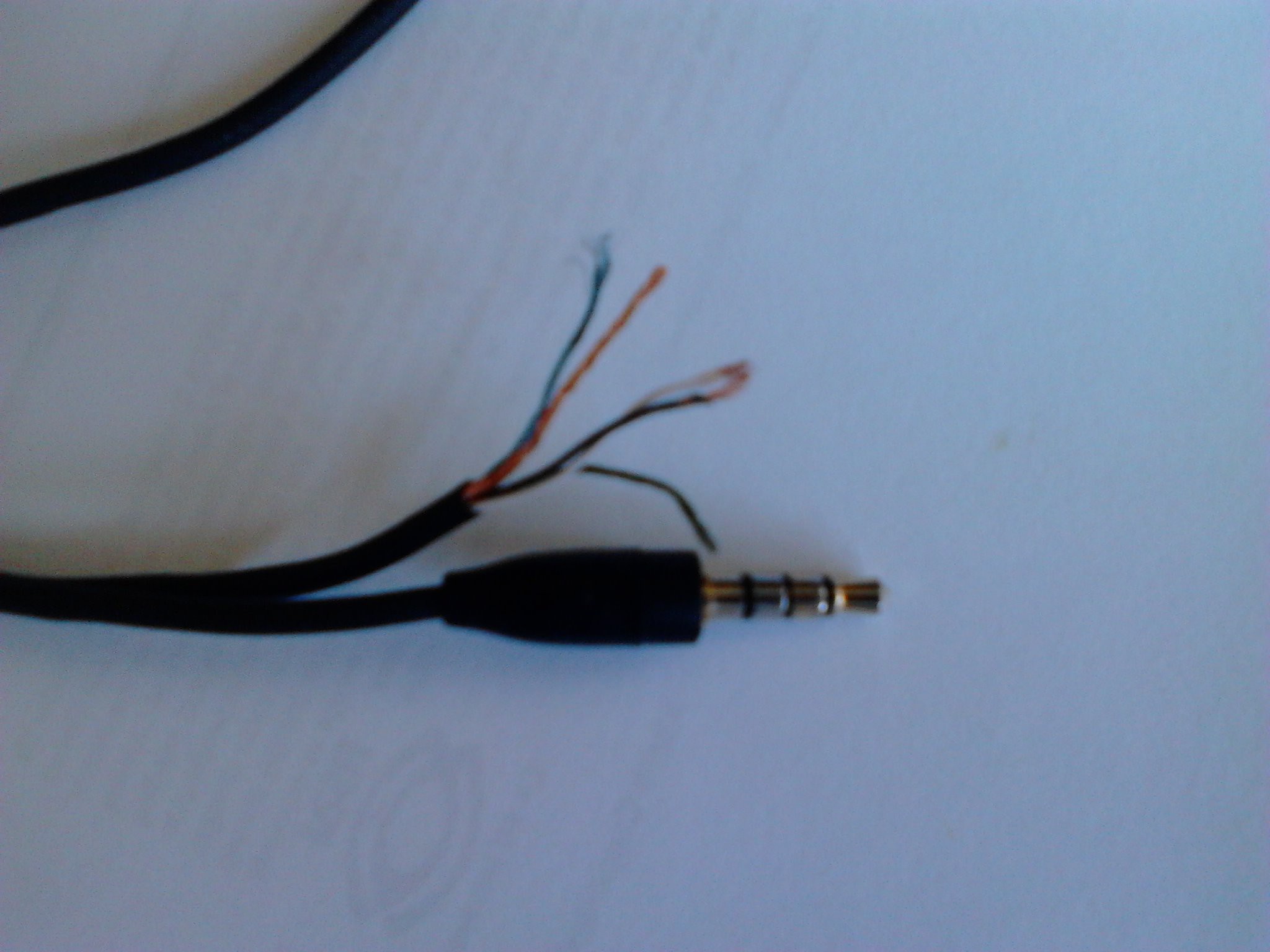
First of all you need to cut the wire, and separate the cables from each other.
![]()
-
2Step 2
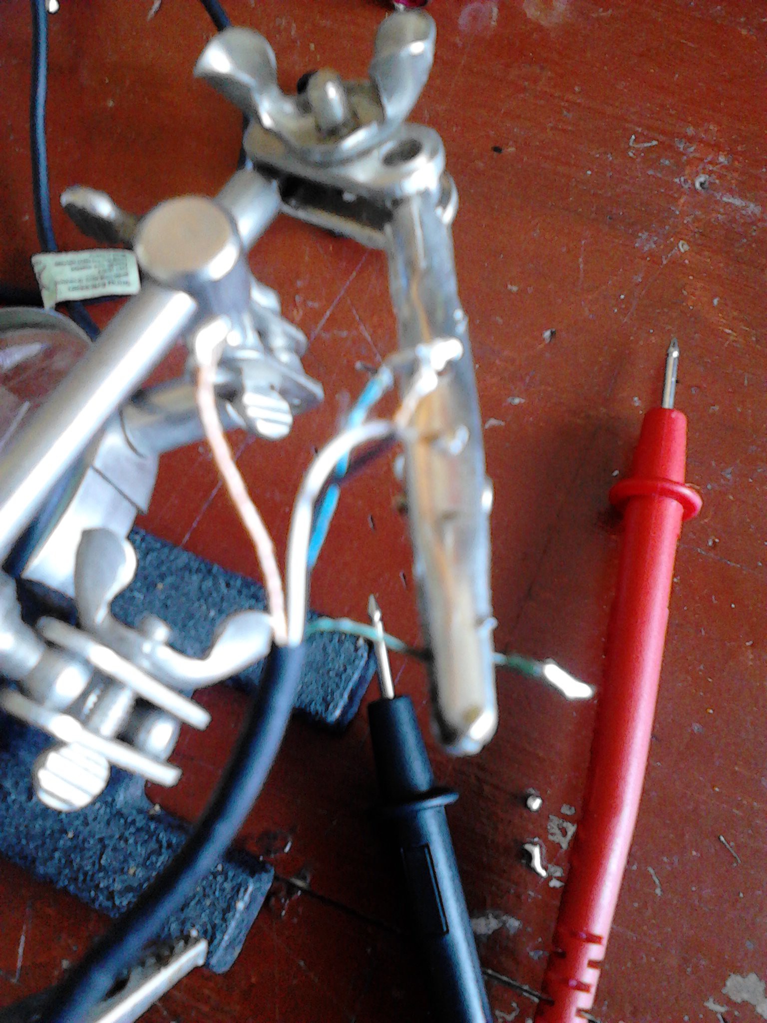
Once you have separated the cables scrape each one with a sharped object in order to remove the thin layers that cover the cables.
Now with the cooper wire visible, you need to put some soldering iron on the tips. That makes the earphone cable stronger on the tips and also you could solder it easily.
![]()
-
3Step 3
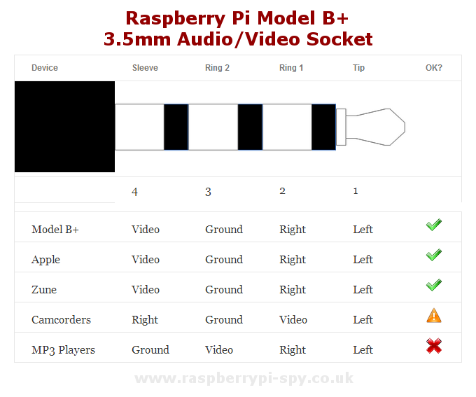
At this step you must test the continuity of the cables, and try to find which one belongs to the VIDEO (4) and GROUND (3), as it's explained in this diagram:
![]()
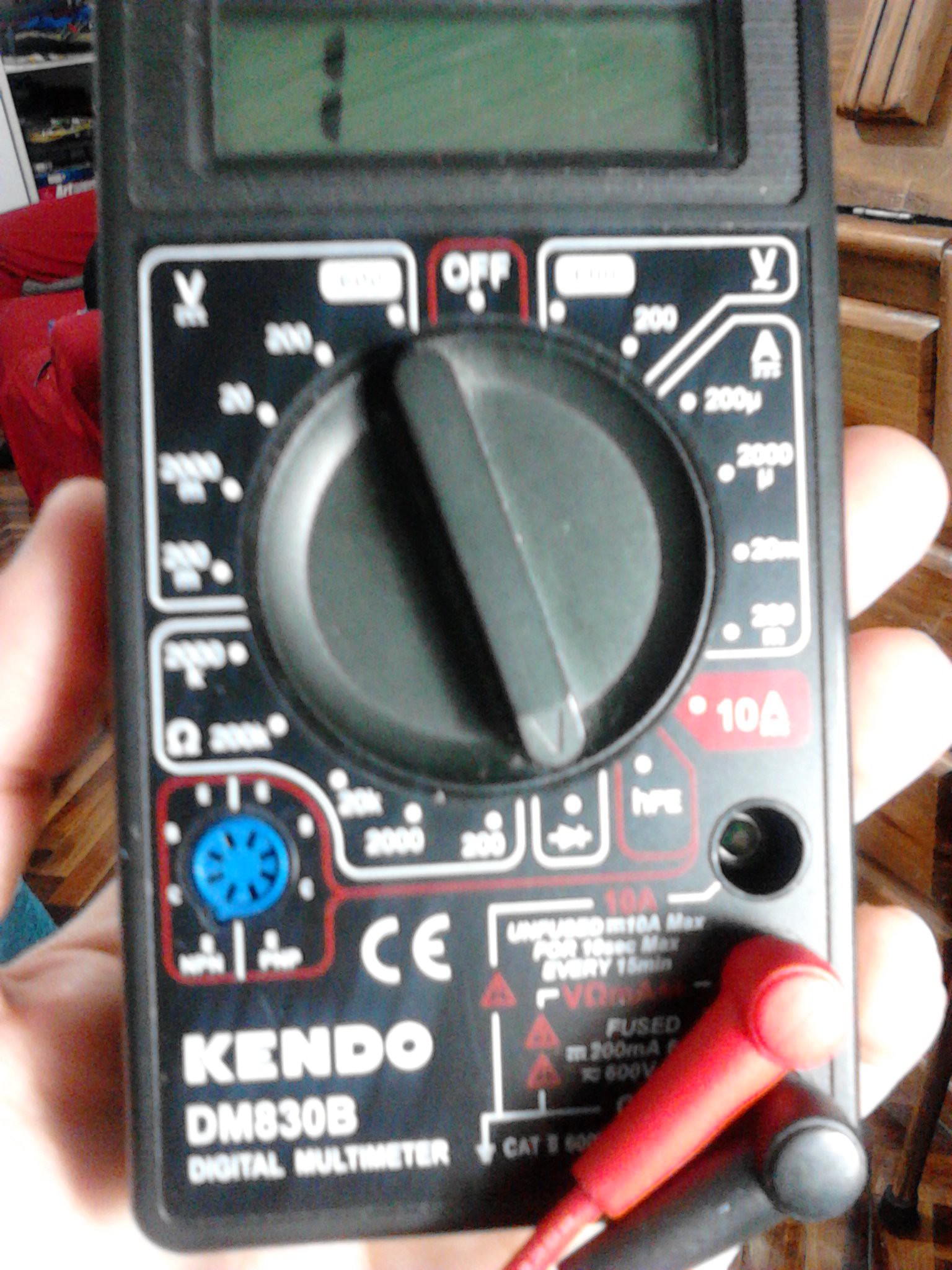
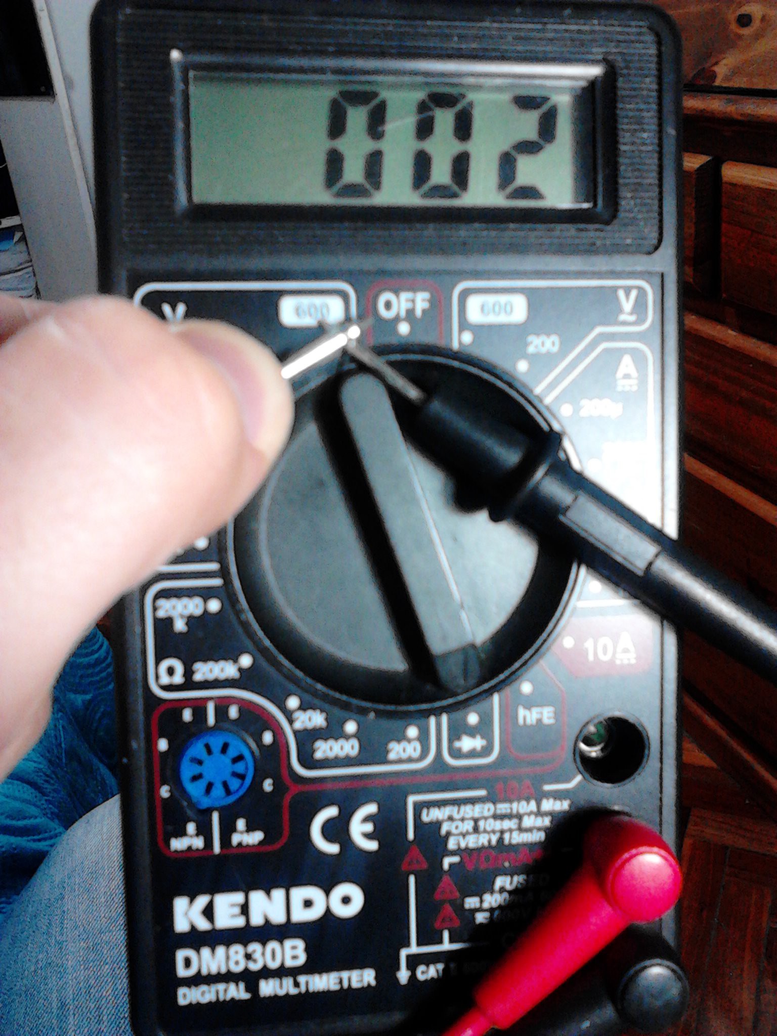
To test continuity your multimeter must be selecting the diode:
![]()
When your multimeter shows:
![]()
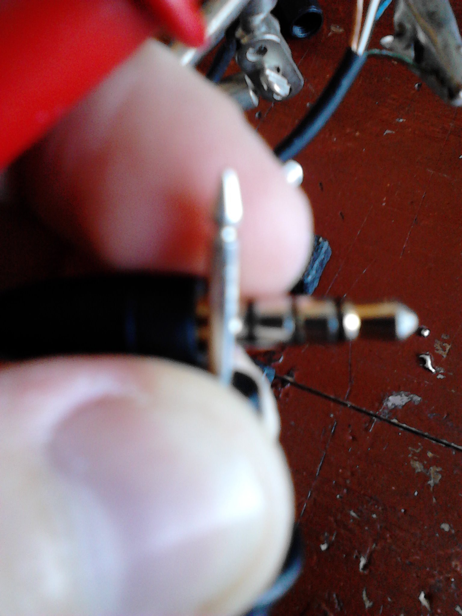
That mean there's continuity, and that cable is connected to that segment of the 3.5 mm jack.
![]()
-
4Step 4
When you have everything tested, separate the cables of the video output and solder it to the Cinch connector, there's an schematic:
![]()
![]()
-
5Step 5
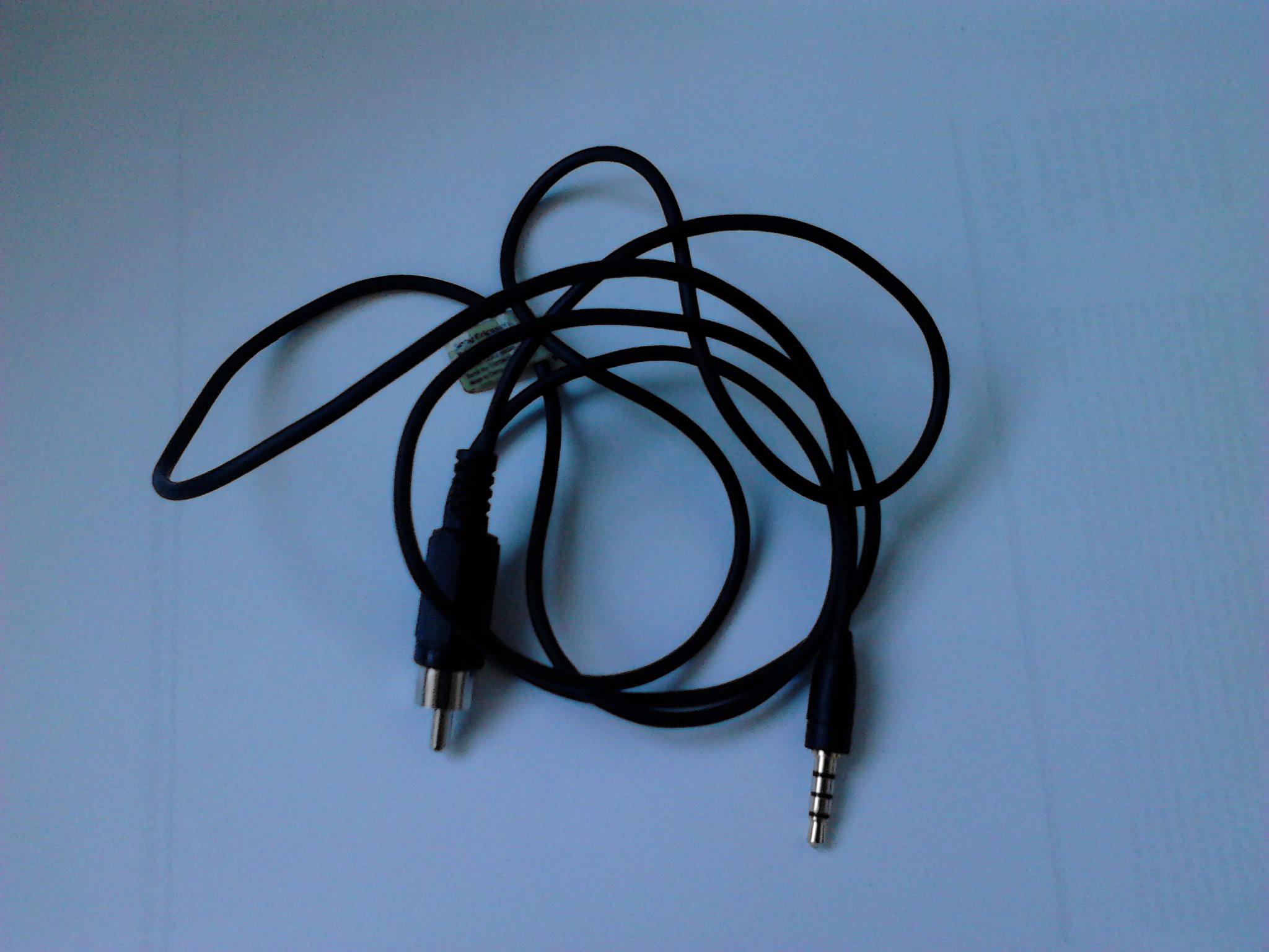
And that's the final product.
![]()
DIY Raspberry Pi b+ AV Out
It's a very simple guide to recycle components to build a raspberry pi b+ AV out component.
 Martin Ferreira


Discussions
Become a Hackaday.io Member
Create an account to leave a comment. Already have an account? Log In.