 Mirrorsails
The main building blocks of this device are:
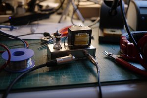
An analog section that correctly biases a microphone, uses a bandpass filter to limit the range of frequencies, amplifies the signal to almost 5V P2P, then adds a +2.5V offset to get the range of the signal 0-5V. If possible, it would be nice if we could use a single sided power supply to power the op amp rather than using two supplies.
An Arduino for its A/D convertor, data processing, and digital outputs. Ideally we will try a few techniques to detect tones from the instrument. The one technique I think will be the winner is the Discrete Fourier Transform, but it will be good to check FFT (if it fits onto the Arduino I don't know), counting zero crossings, and autocorrelation as well.
Finally, an IR LED section to send the correct signals to the TV. Naturally, you can't send a signal without knowing the signal first, so we will also need to read signals from the remote controller that turns the TV on now.
The hope is that after it all works, the basic design can be adjusted for other tone based projects. One idea is a Simon type game with tones rather than colored lights. Another is a game where Oompaloompas are controlled through some course with tones.
 Kris Slyka
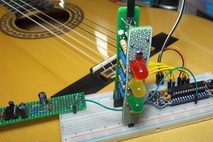
 Paul Gallagher
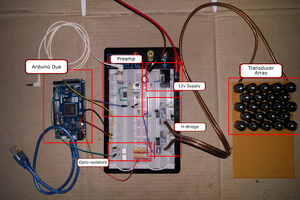
 Alan Green
 joey castillo