 Jean-François Duval
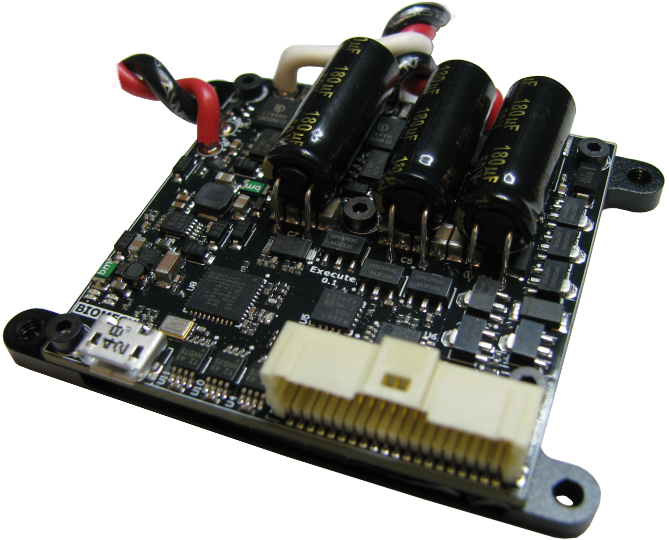
At its core, the FlexSEA-Execute board is a BLDC motor driver. It is specialized for robotic and prosthetic applications. The high level design goals were to maximize the system integration (small physical dimensions, large number of integrated peripherals and interfaces, support for external input and output devices), allow fast communication and networkability via the use of a fast multi-drop communication interface, and have built-in safety features. The design went through three major revisions; this document focuses on the last generation (FlexSEA-Execute 0.1) (for more details (and pictures) about the previous designs, refer to The evolution of FlexSEA prototypes.)
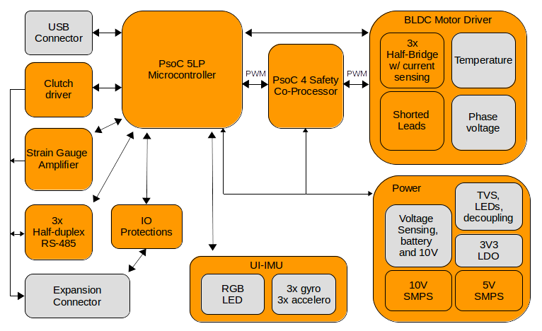
The next figure presents the logical organization of the FlexSEA-Execute 0.1 board. In orange are the schematic sheets and in grey are the sub-circuits present on certain sheets.
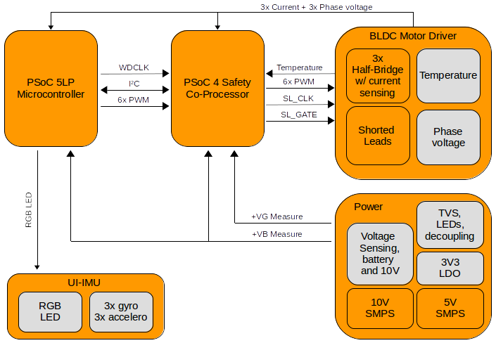
The safety system is extremely important. The next diagram highlights the safety related features:
| Electrical specifications | Supply voltage (V) | 15-24V |
| Motor current (A) | 20A Continuous | |
| Intermediate supply | 10V 500mA SMPS | |
| Logic supply | 5V 500mA SMPS | |
| Motor | Type | 3-phase brushless (BLDC) |
| Sensor(s) | Hall effect, optical encoder | |
| Commutation | Block, Sinusoidal, FOC | |
| PWM | 12 bits 20kHz, 10 bits 78kHz or 9.65 bits 100kHz | |
| Microcontroller | Reference | PSoC 5LP - CY8C5888AXI-LP096 |
| Special features | Programmable analog and digital blocks | |
| CPU/RAM/IOs/Package | 80MHz ARM Cortex-M3, 256KB RAM, 62 IOs, TQFP | |
| Software / IDE | PSoC Creator 3.1, mix of C (ARM GCC 4.7.3) and graphical programming. | |
| Co-processor(s) | PSoC 4 - CY8C4245LQI-483 | |
| Serial interface | Type | 3x Half-Duplex RS-485 (can be full-duplex synchronous) |
| Bandwidth | 2-10Mbps | |
| Onboard USB | Full-Speed (FS) 12 Mbps | |
| Current sensing | Hardware | 0.005Ω resistor |
| Software / control | 20kHz Proportional-Integral controller | |
| Safety features | Overvoltage | TVS will clamp at 36V |
| Overcurrent | Software protection | |
| Locked rotor | Hardware - lead shorting circuit | |
| Motor temperature | Hardware measurement | |
| Board temperature | CPU + bridge temperature reading | |
| Clutch | Variable voltage, 8-bits PWM, 400mA | |
| Strain gauge amplifier | Dual stage, 500 < G < 10000, high CMRR | |
| IO connector | Molex PicoClasp 40 positions, SMD 1mm pitch | |
| External peripherals | IOs available | 12 |
| Digital IOs | Up to 12 | |
| Analog inputs | Up to 8 (12-bit SAR, 8-20-bits Sigma Delta) | |
| Serial | I²C, SPI, UART | |
| Other | 1 optical encoder (A/B/I), 1 Hall effect encoder (3 pins) | |
| Dimensions (mm) | X (mm) | 49 |
| Y (mm) | 49 | |
| Z (mm) | From 12 to 15mm depending on capacitors | |
| PCB technology | Layers | 6 |
| Copper | 1 Oz | |
| Trace/space/via | 5/5 mils trace/space, 8/20 mils blind vias | |
| Assembly | Double-sided | |
| Other | 6-axis IMU, RGB LED |
Discussions
Become a Hackaday.io Member
Create an account to leave a comment. Already have an account? Log In.