 peter jansen
With the parallel radiation detector design the keystone to the whole project, I've been working to characterize the prototype detector performance, and narrow down a solid design.
Taking a step back before jumping into things — in the last post I'd noticed that the detector was reading approximately 20 counts per minute (cpm) from the Barium-133 radioisotope source at a scanning distance of about 6cm. In a way this is fantastic — the detector is working, after all, and with less than a tenth the surface area of the Radiation Watch Type 5. But if we (arbitrarily) set a ceiling of 100 counts per pixel as a baseline in order to reconstruct a good image, we would need to integrate for 5 minutes at 20cpm to reach this. Assuming we're scanning an object 6cm in height (or ~20 BPW34 photodiode-sized 3x3mm pixels tall), it would take about 100 minutes to acquire each image. For the computed tomography component, if were we to take images fairly coarsely at 10° intervals, we would end up requiring 360°/10° or 36 images per complete scan. 36 images * 100 minutes per image is 3600 minutes, which is 60 hours, or 2.5 days. That's light years ahead of the current 9 hours per image, but still a little long — ideally we'd get a complete scan to well under a day.
To help move closer to this, I remembered a trick that my Dad used to use to double the memory in old (sorry, Dad! :) ) computers, where going from 4k to 8k was a huge deal. To do this, he'd order a second set of memory ICs, and physically solder them on top of the existing memory ICs, while lifting one or two pins to hot-wire on a new address line to give access to this larger memory space. I remember this very vividly, not just because we were laughing about it a few weeks ago, but also because when I was at the age where I was taking /everything/ apart that I could get my hands on, he'd given me this sacrificial Tandy Colour Computer that he'd done this to so that I wouldn't accidentally break something more modern, and seeing those stacked chips when I opened up the case was very unusual and memorable.
In terms of radiation detection, the number of detections depends on the area of the detector, and folks often end up using either one large detector or several smaller detectors to get enough surface area for their application. And while more area means more detections, having a larger detector means that we'd sacrifice spatial resolution. But, unlike the visible radiation the BPW34 photodiode was designed to detect, only about 1% of the x-ray and gamma photons are interacting with the detector, and many of the rest are actually sailing right through the detector. Enter Dad's stacking idea — the BPW34 package just happens to be shaped such that it's amenable to stacking multiple photodiodes one atop another, and if we stack multiple detectors, then we increase our chances of detecting these x-ray photons, and should be able to increase the number of detections without sacrificng spatial solution. Sounds great!
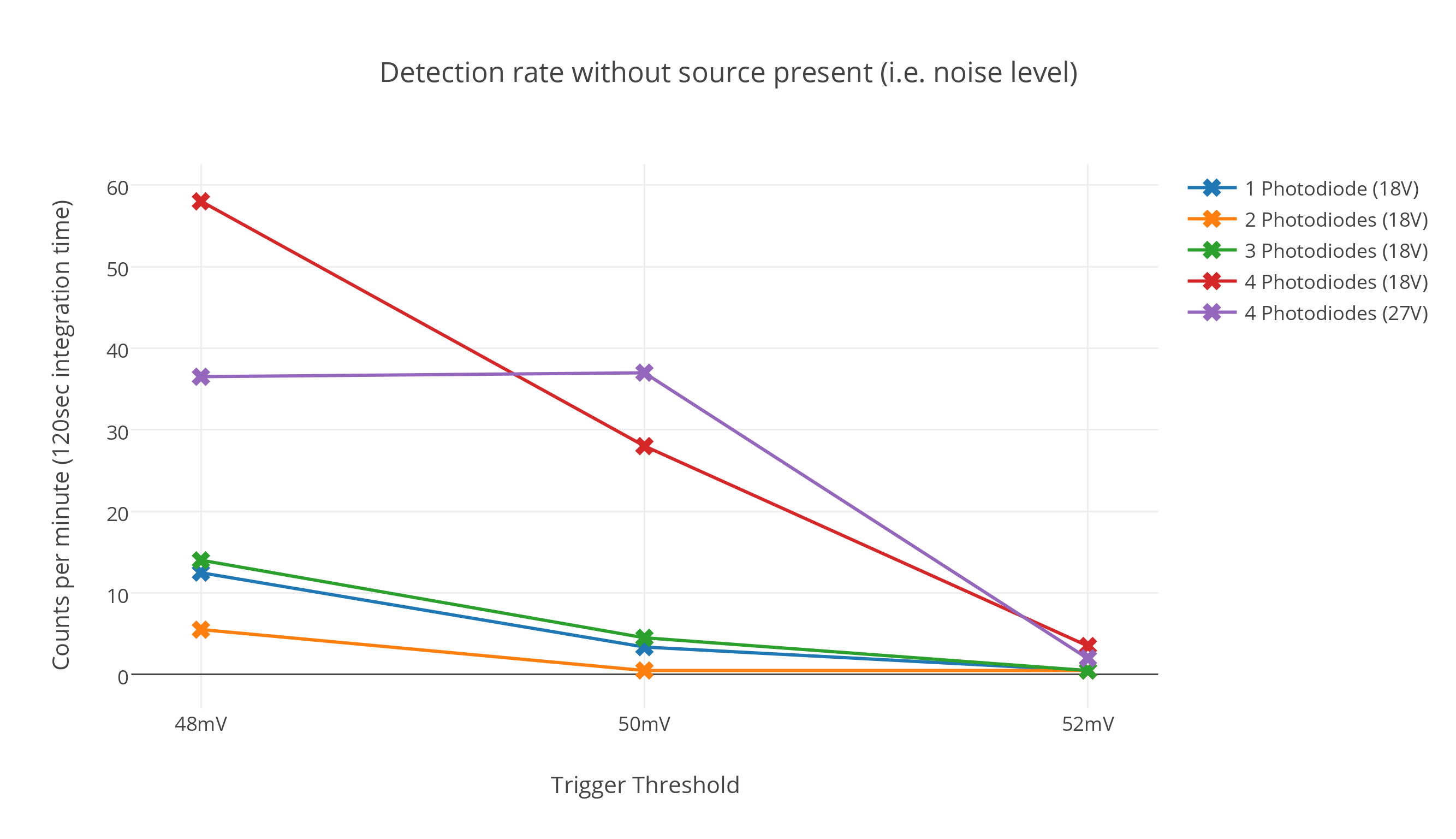
Noise Level
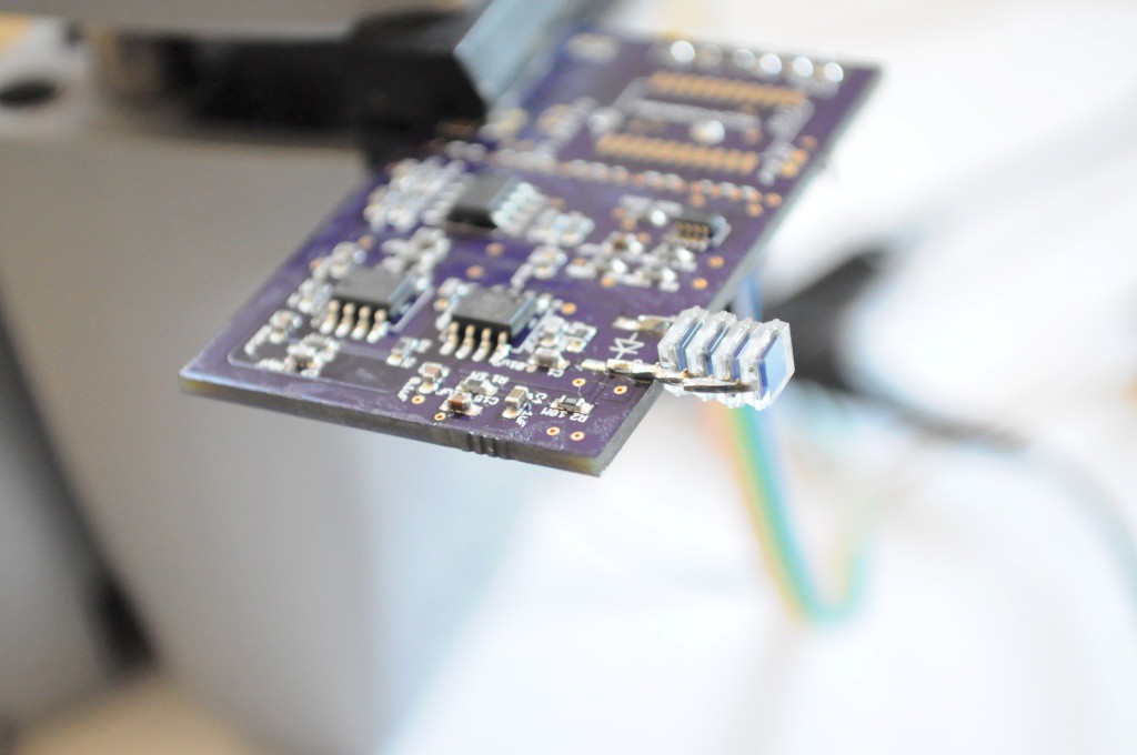
The high-energy particle detector nominally includes three high-level components: A photodiode detector, a very sensitive amplifier, and a microcontroller for counting the detections. The microcontroller appeared to be adding some noise to the process, so I've populated a modified version without the microcontroller, and have been using a scope to characterize the detector.
The noise level (measured in counts per minute) is pictured above, for three different detection thresholds that appeared to be right around my eyeballed noise threshold of ~50mV. Here we can see empirically that the noise threshold is infact around 50mV, with a near zero number of counts at 52mV, a very small number of counts at 50mV, and many more counts at 48mV.
Interestingly, the number of photodiodes doesn't appear to affect the noise too much until we reach 4 photodiodes, where the noise level increases quite a bit. Here I've included data from 4 photodiodes at both an 18V bias (ie. two 9V batteries, red), and a 27V bias (purple). So in terms of noise, 3 photodiodes and a ~50mV trigger threshold seems to be a good balance of photodiode surface area vs noise level.
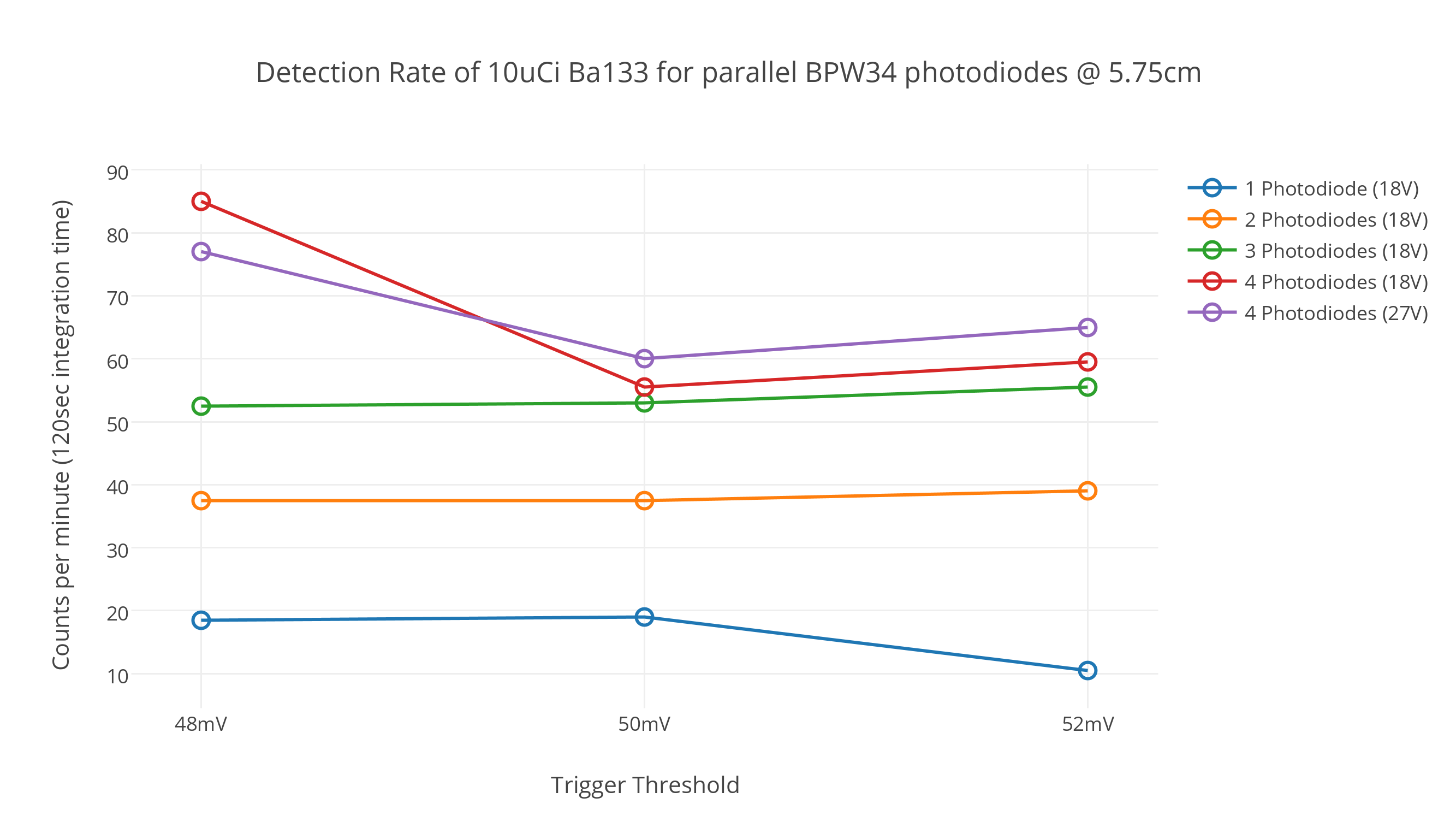
Signal level
The signal story is very similar, though with a bit of a twist. Above we see the signal level (in counts per minute) with the 10uCi Ba133 radioisotope source about 6cm from the detector — enough for the 2 inch sample container with a bit of a mechanical buffer on either side. Here each line represents the difference between the number of detections minus the noise figures from above, so what we're seeing here is just signal level, without the noise.
Quite wonderfully, we see approximately linear gains when we stack the number of photodiodes, up to 3 photodiodes. Where a single photodiode detects approximately 20cpm (blue), 2 photodiodes detects just under 40cpm (orange), and 3 photodiodes detects about 55cpm (green). The story gets a little more interesting at 4 photodiodes — for 50mV thresholds and higher the detection rate goes up only a small amount to 60cpm, but for a 48mV threshold (well into the noise), the detection rate increases to approximately 80cpm. It's not entirely clear what's happening here, but it looks like 4 photodiodes would be a safe bet — approximately 60cpm at a 50mV threshold, with the possibility for increasing it a good deal lower if we venture into the noise.
How does this affect the scan time? At 60cpm, we would need only 100 seconds to reach a ceiling of 100 counts, about 30 minutes per image, and 20 hours per 36-angle (10° rotation) scan — much faster than before. In the best case if we assume that we're able to get 80cpm and integrate for only 1 minute per measurement, it would take 20 minutes per image, and 12 hours per scan. This seems to be about the limit (currently) of these radioisotope check source methods: (1) We're using a Ba133 source with emissions that are low enough energy to be most efficiently detected while being just slightly above the noise floor, (2) We're using the maximum amount of this material (10uCi) that can be purchased without a license, (3) The diodes in the detector have been stacked until the edge of diminishing returns, and (4) The scanning volume has been reduced to the minimum usable size. Without significant advances in the way we go about detecting these high-energy particles this is likely pretty close to the best that can be done with such a low intensity source, and raising the intensity of the source (say to an x-ray tube) treads into nuclear safety, regulatory, and legal issues that I'm simply not comfortable with. Given that all the limits have been pushed, 12 hours for a complete scan is much better than the original figure of several weeks, and definitely something I can live with!


Oscilloscope Traces (and measurement noise)
I've captured a few example detections using a Rigol DS1054Z oscilloscope. As near as I can tell this scope isn't capable of counting how many times it has been triggered per unit time, so I connected the trigger output to an Arduino Uno to calculate the number of detections (or counts) per minute (cpm) in the above graphs. Interestingly, I'm not sure whether it was the Arduino Uno or the USB port the Uno was connected to, but this seemed to add bursts of about +/-10mV of noise on the signal every 8 to 12 uSec (this can be seen on the two traces, above). The Arduino Uno clock is 16Mhz which would give a clock period of ~6.25uSec, and USB 2.0 is (I believe) 12Mhz which has a period of 8.3uSec, although I'm not sure why the period of the noise jitters. In either case, the actual noise floor of the system is about 10mV lower, as can be seen on the graphs below, without the Arduino connected.

This trace (above) looks typical of a high-energy particle detection, likely from one of the higher emissions of Ba133. Because of their energy (and the high magnitude of the detection peak), these are relatively easy to detect.

The lower emissions (likely around 30-35keV) are much more challenging to detect, and their amplitude is so small that they look very similar to the noise. I believe the trace above represents a noise detection — given the surrounding waveforms one might be tempted to believe that the noise floor is only around +/-20mV, but many of the peaks (on the scale of seconds and minutes) reach to 40mV, making this the effective noise floor.
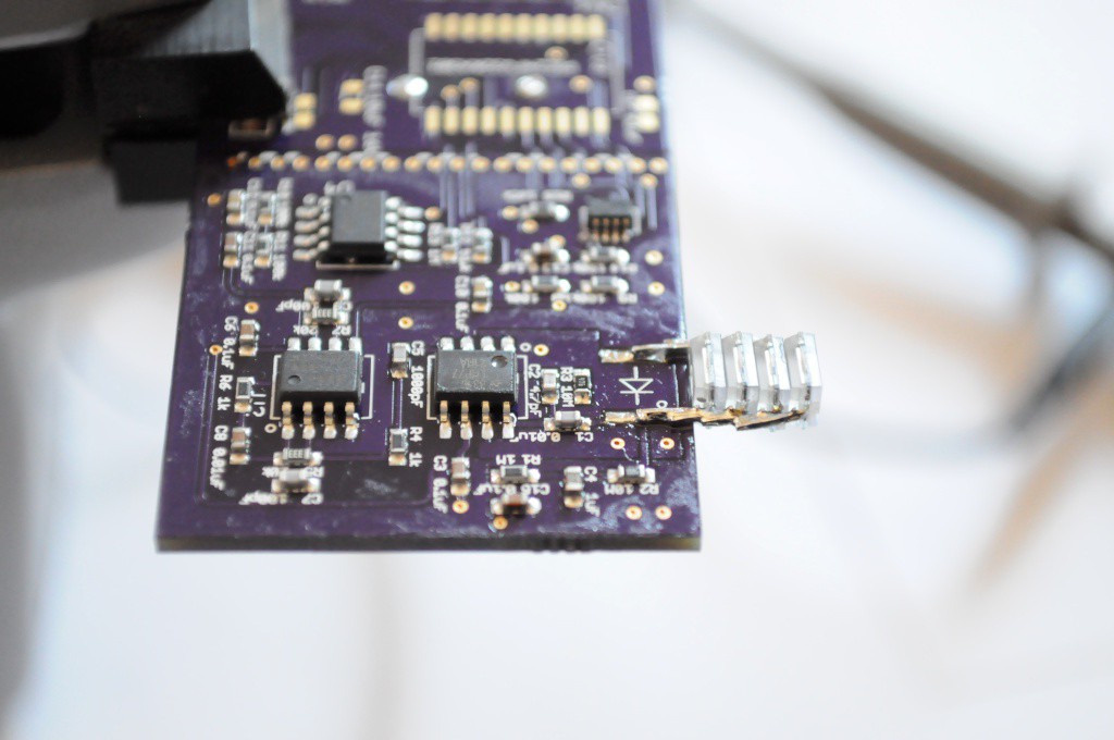
And so, using this preliminary performance characterization, it looks like we're close to nailing down a final design for the detector, and one with much better performance than I was expecting. To accommodate the extra photodiodes I'll have to modify the PCB to extend out another 5mm, and include a slot and pad that the photodiodes can slide into for (ideally) relatively easy surface-mount soldering. In the worst case, if a few of these diodes do have to be hand soldered, a few seconds of soldering is a very small price for 3-4 times the performance. Still, the memory of spending days and days to solder each set of Arducorder boards is fresh in my memory, and I'm endeavoring to design these modular detectors to be as simple and inexpensive to assemble as possible. Removing the microcontroller and adding in the parallel photodiodes, the parts cost in low quantity is about $25 each, about half of which comes from the extremely low noise TI LMP7721 precision opamp. Given that the detector is currently operating right at the noise threshold, I'm hesitant to substitute this part for a less expensive opamp, but with TI as an official sponsor of the Hackaday Prize and an array of detectors to build, perhaps they'll be able to donate a tube of these parts to the cause of open source science.
Mechanical Design
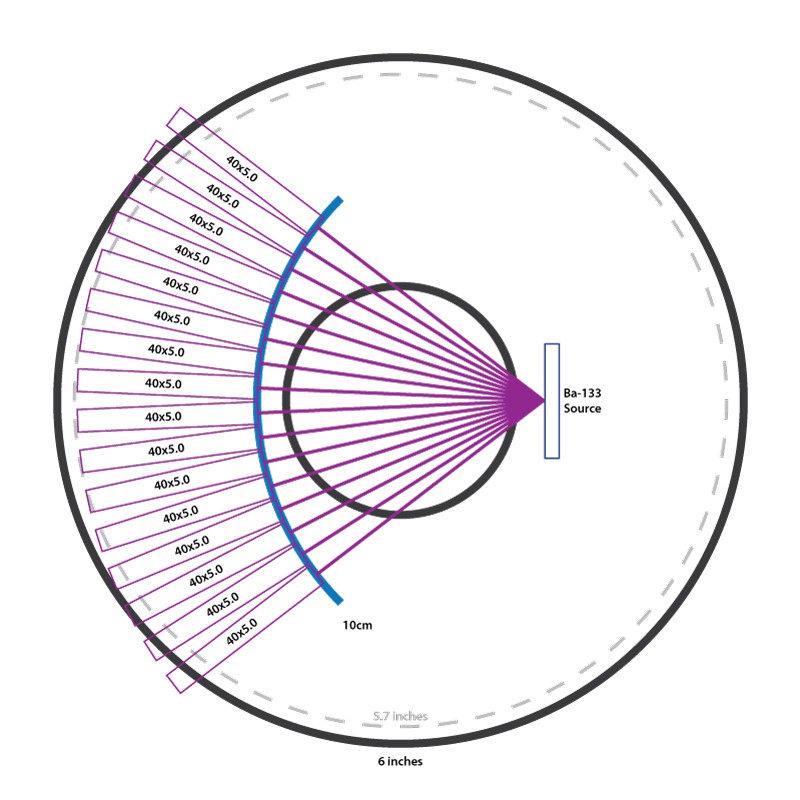
With 4 photodiodes, the current detector design extends to about 40mm in length, and (after wrapping with aluminum shielding) about 4.5mm to 5mm in thickness. With a 2 inch acrylic sample container, and a ~3mm buffer on either side of the container, this allows a packing density of exactly 16 detectors over a 75° fan angle from the source.
For compactness and supply, I'd like to keep the design to within 6 inches in diameter — and 6 inch cylinders of various sizes are much more easily found (and much less expensive) than moving up to 8 inches. Home Depot even carries a fairly hefty 6 inch (~5.7 inch ID) drain pipe that's inexpensive, extremely sturdy, and would be perfect for prototyping case designs with. Unfortunately 40mm detectors are a bit too large to fit within this size — it looks like the detector would have to decrease to 30mm or less to squeeze into a 6 inch cylinder.
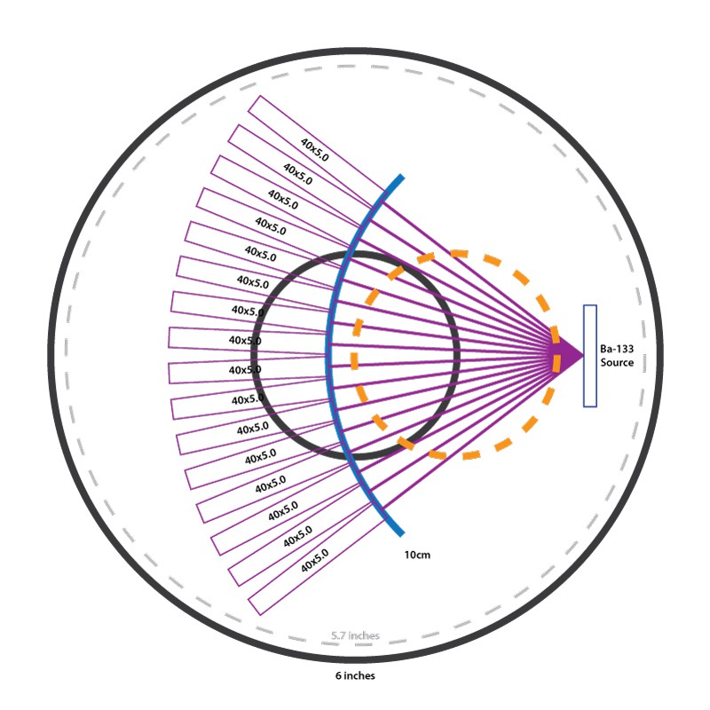
Another option, shown here, is to throw symmetry to the wind and slightly offset the sample container, giving the whole unit a clear "front" and "back". This is a fairly simple solution, and I'd like to include a front display panel for the device as well — so if several stepper motors and lead screws can effectively fit into this footprint, it might be a very good solution.
Thanks for reading!
Discussions
Become a Hackaday.io Member
Create an account to leave a comment. Already have an account? Log In.