Sea Temperature Sensor using GSM
A template for battery powered sensors using GSM
A template for battery powered sensors using GSM
To make the experience fit your profile, pick a username and tell us what interests you.
We found and based on your interests.
"Sea Trial" two has been going on since Sunday 14th of June. I installed two units, one on a buoy at St Heliers Beach and one at neighbouring Kohimarama Beach. The two units are slightly different, one has the same external antenna used in the first trial, the second has an internal antenna. The intention of this difference was to confirm if the signal strength was going to be sufficient without having to put another hole through the waterproof case.
See the results:
Read more »Version one was tied to a "5 knot" marker buoy with some string: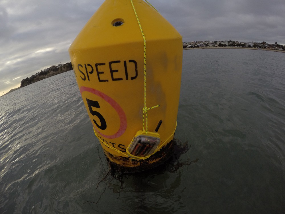
This was effective, but not ideal. There's no way to remove the sensor without undoing everything. It's hard to tie knots when you're bobbing around in a wetsuit in the water. And it just doesn't look good.
So time to find something better!
Read more »After a successful first deployment it's time to work on the battery life.
I already had some ideas for how to reduce the power usage, so time to start working on them:
Time to stick it out in the water!
The code is unchanged from the bench test except for adding an extra 5 minutes to the delay to get ~10 minute updates instead of the 5 minute updates on the bench test.
The hardware is also basically unchanged from the bench test. It now has two batteries, fresh off the charger, wired in parallel. They are held in a 3D printed battery holder.
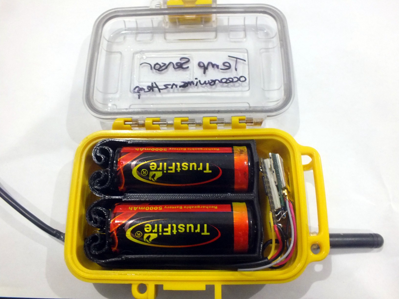
On Saturday 30th of May 2015 I threw the sensor and some cord in my swim bag and did a normal couple of kilometer training swim with friends. Afterwards Rosie and I swam back out to one of the "5 knot" marker buoys 200 meters offshore and "mounted" it.

Okay, so "mounted" is a bit generous. It's tied one with some cord, and has some labels scribbled on it so it doesn't look too much like a remote trigger for a bomb.
It ran smoothly for a bit over 12 days!
Only a couple of data points were missing (likely GSM connectivity issues). The datasheet said the Sim800L would operate down to 3.4v and that was spot on. It sent three readings at 3.402v, then went quite for a while then one final reading at 3.391v.
A couple of days later a pre work swim allowed me to retrieve it. When inspected then enclosure was not 100% dry, there was some moisture present. I'm not sure if this was condensation from when it was closed up, or if it got in while installed. The gasket wasn't totally clean so it's possible that's how some water got in.
Let's call that a success and time for version two!
Before installing the first prototype in the sea I wanted to run it for a while to see what the battery life might be and ensure the code doesn't mysteriously die after a period of time.
A teensy 3.0 connected to the cheapest Sim800L breakout I could find. This breakout has the Tx/Rx, Power and Reset pins broken out. A simple resistor voltage divider on the Rx input of the Sim800L takes care of level shifting the Teensy's 3.3v to the needed 2.8v IO.
The way the breakout for the Sim800L is wired, the module turns on as soon as it gets power. The plan was to tell the module to power off when not being used then use the Reset pin to bring it back to life. I wrote some quick code, wired up the Reset pin to a digital IO pin on the Teensy and I could turn it off, then reset it to bring it back to life so moved on to the rest of the code thinking this was sorted - more on this later.
Next was making an HTTP request, there's plenty of code examples for making a TCP connection and sending HTTP requests with the Simcom GSM modules. Then I checked the datasheet and found it had HTTP request support build in (why doesn't everyone just use this?). So making an HTTP GET request is pretty trivial, I hacked that up and had it sending me temperatures ever minute shutting down the module in between, it worked okay (code was a mess but worked - optimised for implementation speed?).
Next was to leave it going longer with 10 minute updates. So I changed the delay at the end of the loop and tried it out, first a delay() that long was coming up short, 9 x 60 second delays worked so that's what I used. The first data came through, the Sim800L turned off. All looked good. Then the Sim800l turned back on! I checked the serial debugging, I didn't turn it on! Turns out the way the breakout board is wired it always turns back on about 30 seconds after being powered down. In my earlier tests I was resetting it before it had time to auto start so I didn't find this. Nothing I can do about this on this breakout, so I've got to live with it.
New plan, put it in flight mode when I don't need it - the lowest power mode in the datasheet that I could use - then put it back in normal mode when I need to send data. So that's what I did:
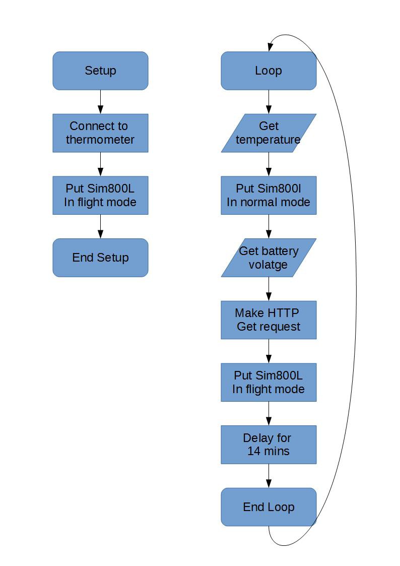
Everything worked fine! I set it at ~5 min updates and gave it a single half used battery and left it running for a couple of days outside in the rain and wind.
Extrapolating the battery voltage drop to two fully charged batteries and ~10min updates suggested 10 days battery life was possible. That was good enough for now, time for sea trials!
Create an account to leave a comment. Already have an account? Log In.
There's always the option to take down the whole circuit for longer periods of time with this chip/breakout board: https://www.adafruit.com/product/3435
This should save more power than everything else...
Hi! Awesome stuff!
Do you mind to upload drawing of a full circuit?
What voltage regulator are you using to go from 3.7V to 3.3V for ESP? And what for SIM800L or its powered straight from battery pack?
Cheers
Mike, I have the same SIM800L module and I'm trying to make it work with 3.3v arduino pro mini (similar to Teensy). I'm having problems with Logic Level Tolerance and I only receive junk characters. In description you explain: "A simple resistor voltage divider on the Rx input of the Sim800L takes care of level shifting the Teensy's 3.3v to the needed 2.8v IO.". I would like to know how did you solved it. I've made many attemps with resistors to pull up and pull down the signals, with no luck.
Any advice will be welcome!
Hi, just a 1K between the TX of the Sim800l and the RX on the Arduino is all you'll need to receive data from the module. If you're receiving junk characters then you've probably set the bitrate incorrectly. The modules I've purchased have all had auto baud enabled so I just send a few new lines to it and it works out the data rate.
I also use the Arduino Pro Mini 3.3v for this instead of the teensy. I use a 5K6 resister between the sim800l RX pin and GND, and 1K between the Arduino TX and the sim800l RX.
HTH
Yes, you're right, it was bitrate problem. My module speed was 115200 and with 3.3v arduino I couldn't slow it down to 9600. But I'm not using a resistor between TX of the Sim800l and the RX on the Arduino. Do you think it's better to add one? it reduces consumption?
Hi Peter, yeah I though about that. The mechanical issues (need for more holes through the waterproof case, and storm proofing it) and cost (panel + charging circuit) are the main reason I haven't pursed it.
It would certainly make a big difference though, most of the time the drain is < 6ma.
Great stuff! I'm sure you've already been asked this before, but would it be possible to use a small solar panel to extend it's life? Or is the drain just too much?
Become a member to follow this project and never miss any updates
 Nikola
 mikrotron
 MCenderdragon
Great stuff mate. This gave me ideas for my low power portable gps tracker project. Thinking of using a FET to cut power, and get the device down to micro amperes in deep sleep.