 BlueMate.com
-
11Step 11
Add Module
![]()
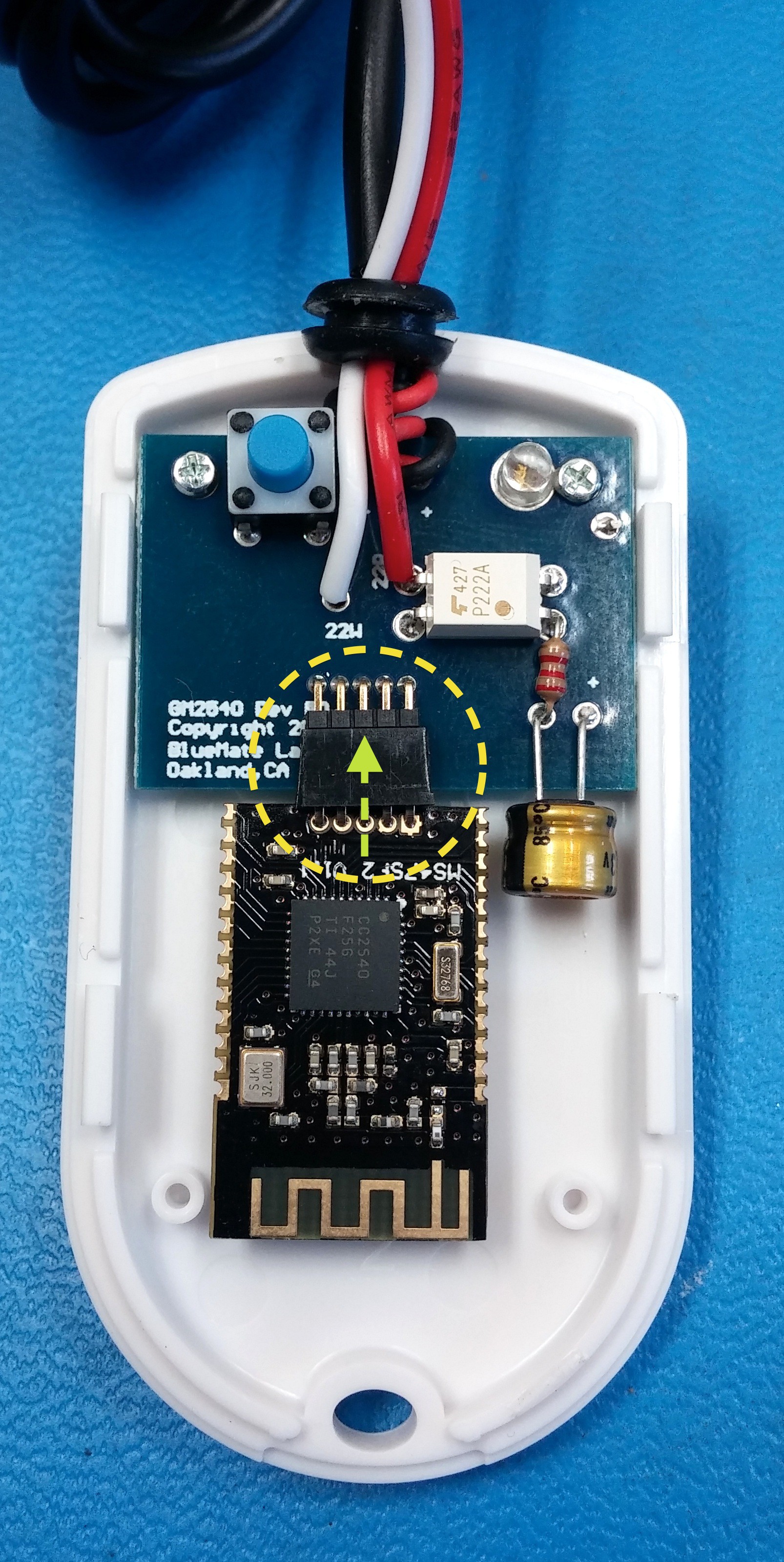
Peel the backing off the adhesive tape on the Bluetooth module and at a slight angle carefully slide it on to the header pins of the PCB. Lightly push the module down to "stick" it to the case.
-
12Step 12
Complete Case
Carefully align the top of the case and "snap" it together. Test pushing the switch a few times, it should easily click in and out thru the hole. If the switch hits or gets stuck on the hole, open the case and adjust the position of the PCB by adjusting the screws, there's a little "wiggle room" to play with.
![]()
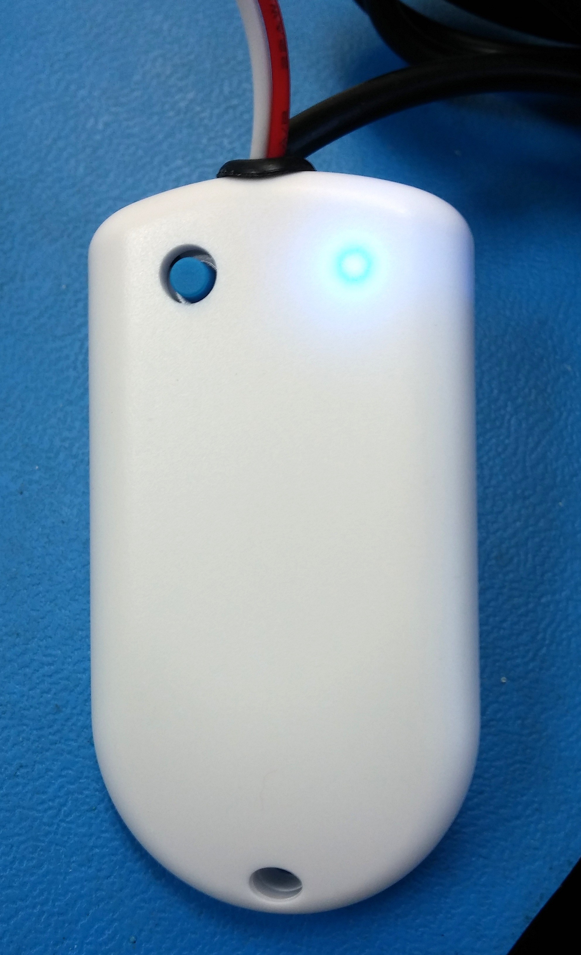
CONGRATULATIONS you've assembled your new receiver!
Now you can test it by plugging in the power, and clicking the button, you'll see the blue LED come on for a second. You'll also see the LED flash once every few seconds indicating normal operation.
-
13Step 13
Complete Setup & Install
You can now proceed to pairing and wiring to your garage opener as detailed here bluemate.com/support.php
![]()
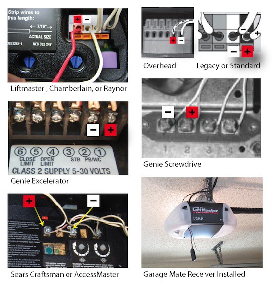
Common wiring diagrams for garage openers, connect the red and white wires to the terminals shown.
![]()
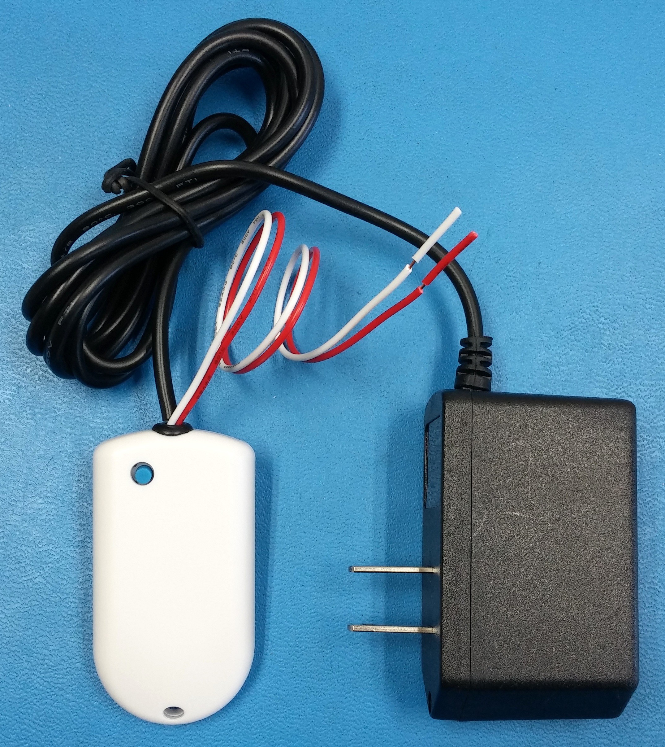
GarageMate DIY Kit
Build a receiver to open/close your garage door with an app. Visit BlueMate.com
Discussions
Become a Hackaday.io Member
Create an account to leave a comment. Already have an account? Log In.
Hello, I'm trying to do this because I've already bought one bluemate and wish to have another one to my parents home, but my county's customs are way too slow and takes fees on 40% of the total. So I'm trying to build one myself, but it isn't working, maybe because I need to program the Bluetooth module, if that's the case I messed up buying all this components. :
Are you sure? yes | no