 Alpha Charlie
[Update: 2015/08/13] - Was out sick and my project updates suffered. Apologies to anyone who's been waiting for an update. My previous 'Sl33p i5 f0r th3 w33k' pace will likely now resume.
This was a very complex project with a lot to it. Most of the circuit modification to the Roland TR-626 are documented elsewhere. (Notably at - http://www.burnkit2600.com/tr-626-rhythm-decomposer/) The main difference between those projects and this one is the use of the Arduino Mega to control an addressable solid state switch array. instead of using cables.
Basically the patch-a-tron is a 'cable-less' patch bay.
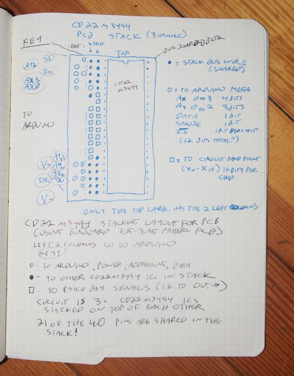
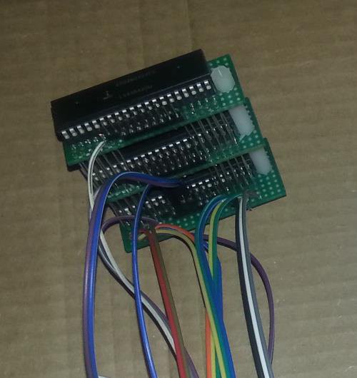
The 3 CD22M3494 cross point switch array ICs share 18 of their 40 pins: V+, Gnd, the 10 switch address pins (4 bits for the x axis and 3 for the y), and the 8 x axis switch pins are connected in parallel for all 3 chips. Since they share so many pins it made sense to stack them.
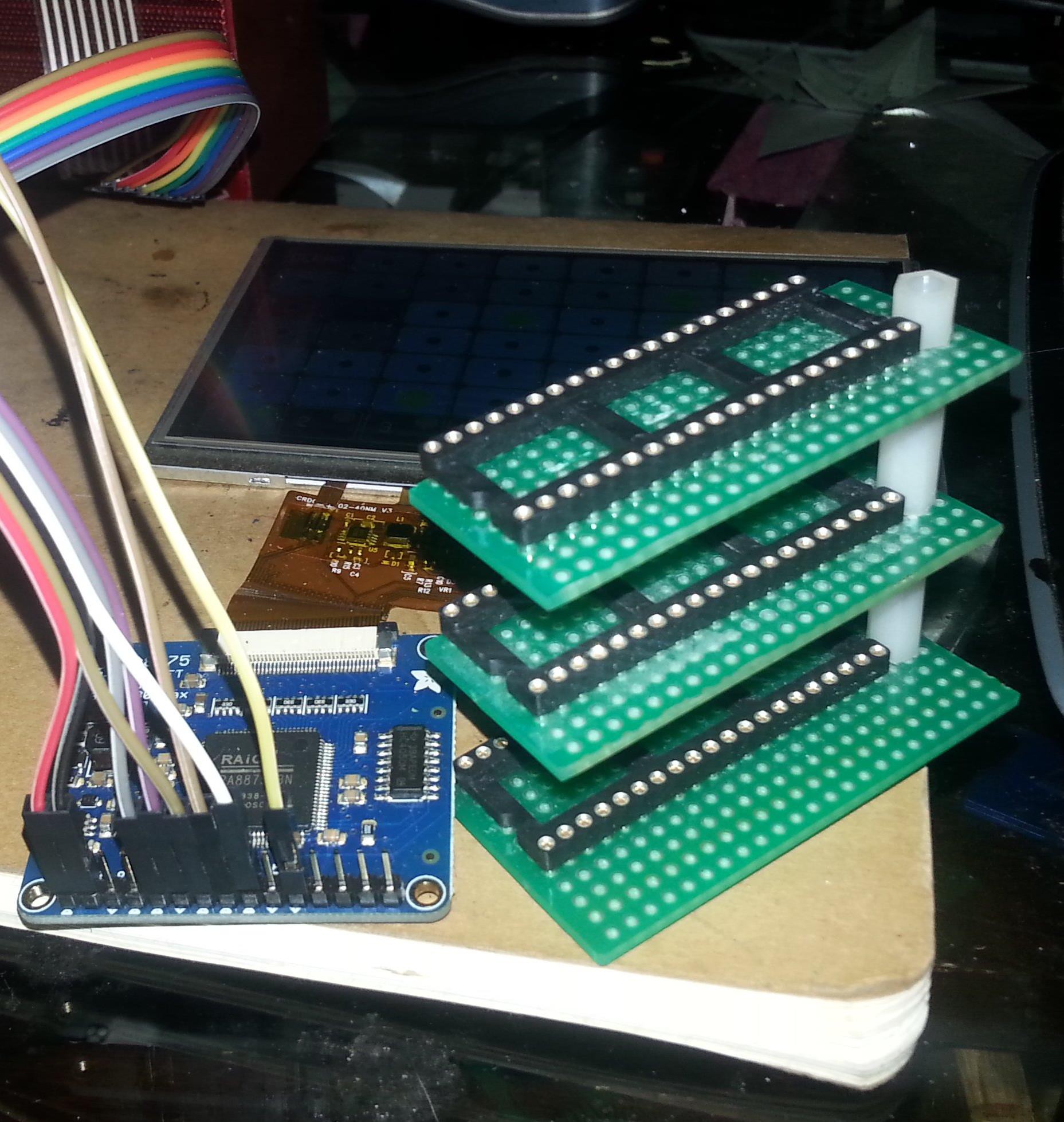
16 wires from each chip are available for the patchbay. That's 48 switches on each bus. Since we have 8 buses, that's 384 switches we can control. To make it easier to navigate this is broken up into 8 screens, one for each patch bus. The switches are represented on the screen in a 6x8 grid. There's another row of 8 numbered buttons at the bottom that select which bus is displayed as well as activate or deactivate the switch configuration (the green dot means its active a red dot means it's inactive.)
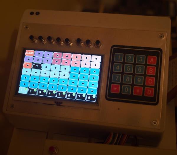
The keypad on the right allows patterns to be saved into the EEPROM and recalled instead of having to remember what cable was plugged into which patch port. It also means that patterns and changes can be triggered by MIDI. (That's right. It has MIDI in too!)
The Analog switch array is configured as 48x8 with the 48 points being used for patch points on the Roland. (I'm actually only using 47.) The 8 axis is 8 'buses'. So the screen shows all 47 patch points that can be connected and the 8 buttons select each independent 'bus'. All 8 buses can be active at once. But only one is visible at a time.
In addition, it's got some safeguards that prevent a user from entering combinations or bends that are capable of crashing or damaging the Roland. For example The software will not allow the user to connect the positive voltage (Row 3 column 1) to the negative voltage(row 3 column 2) as that would short circuit the power supply. Other 'known bad' combinations are also disallowed. Similarly, the 8 'buses' will attempt to avoid each other. (i.e. if 2 bends contain the same bend point, only 1 can be active at a time. ) This helps keep the sound from turning to 'mush' during complex bends or sequences.
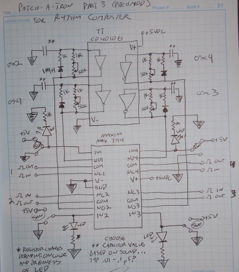
Please bear with me while I compile all of the documentation for this project and add it this page. I'm adding things as I come accross them.
Source code for the 'patch-a-tron' is up an Github and should be helpful to anyone looking to use the CD22M3494 with Arduino. It basically uses 7 address bits to select the switch address, one to set it's state, a strobe and then one CS pin for each CD22M3494 chip used. The circuit uses parallel addressing (i.e. all of the chips are hooked up to the same address pins on the Adruino.) The CS pin on each IC is used to select which chip the Arduino is setting at any given time.
This project is released under the MIT license - http://opensource.org/licenses/MIT also available on the project github page


 Hulk
Hulk
 Thomas
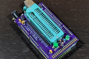
 Eric Ljungquist
thanks! I should have the remainder of the patch-a-tron schematics up by this weekend.