 M.R. Inc
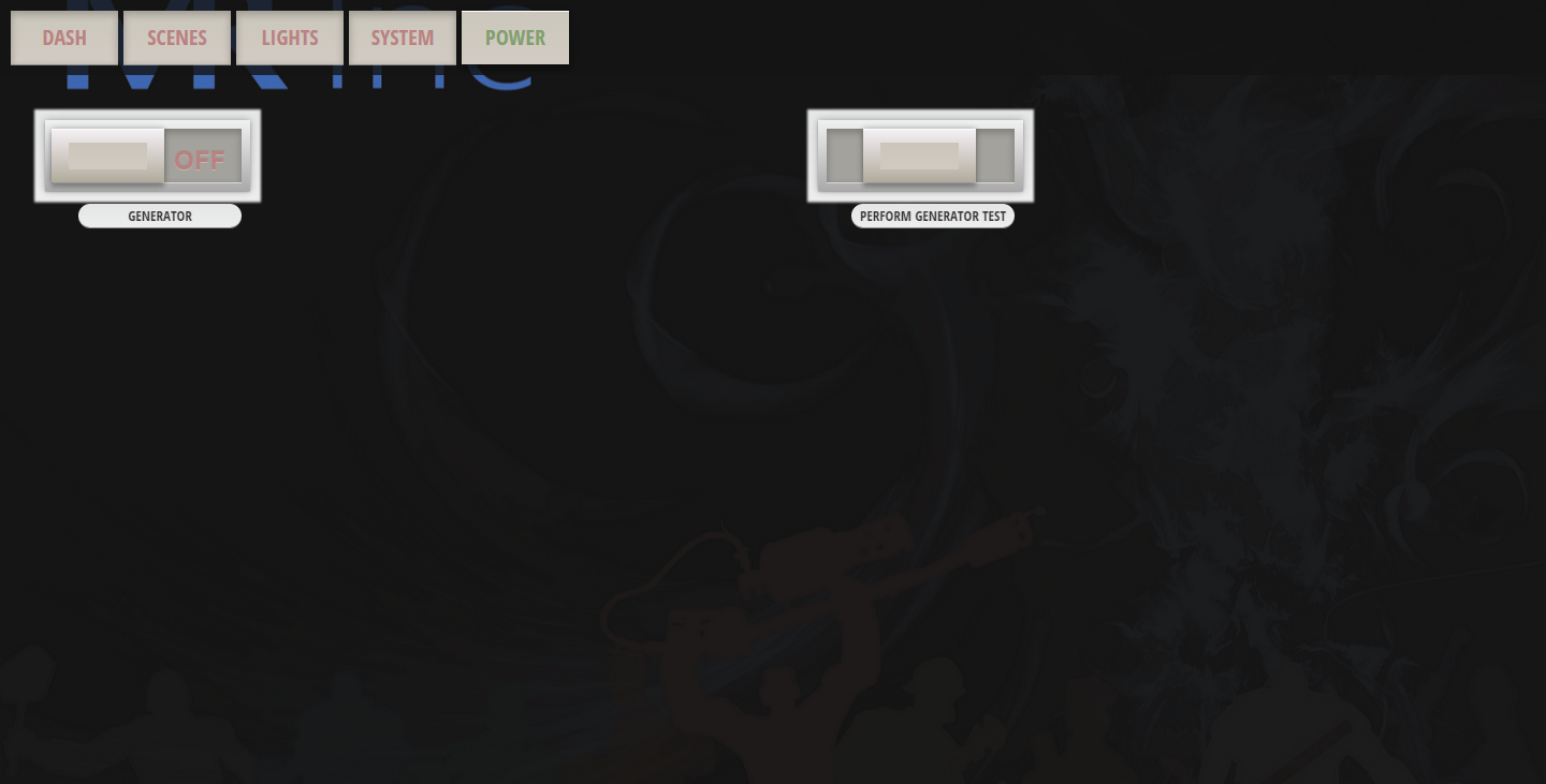
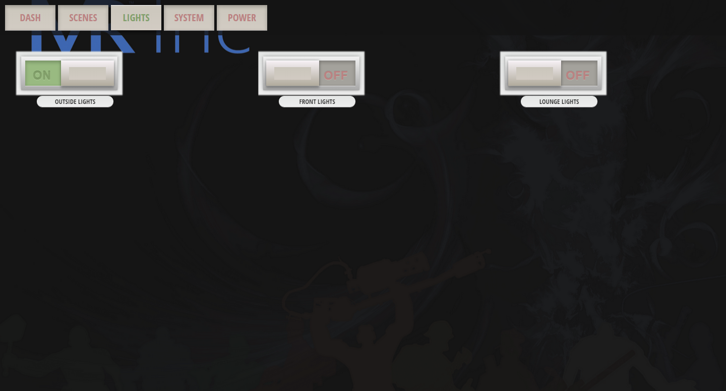
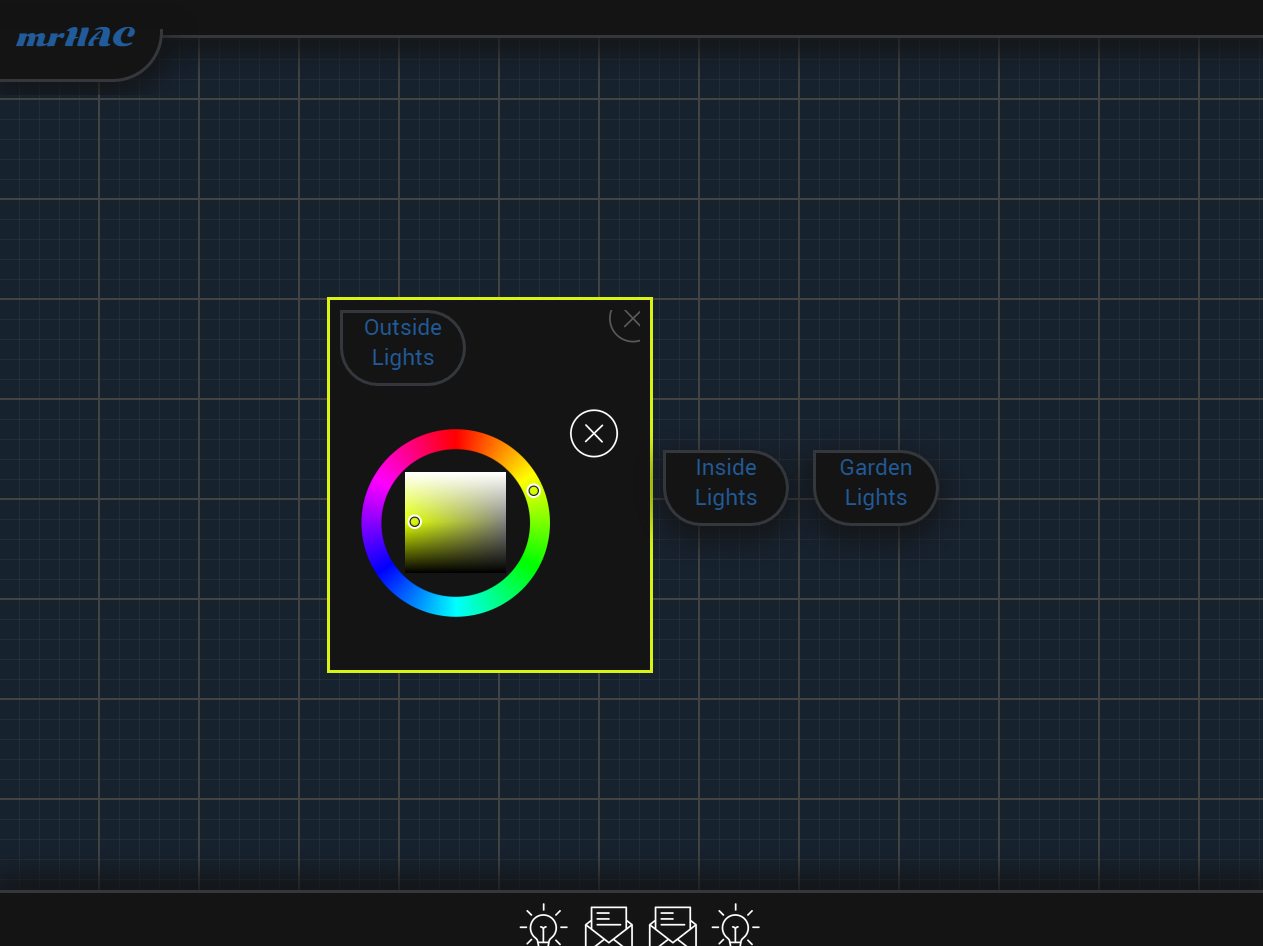
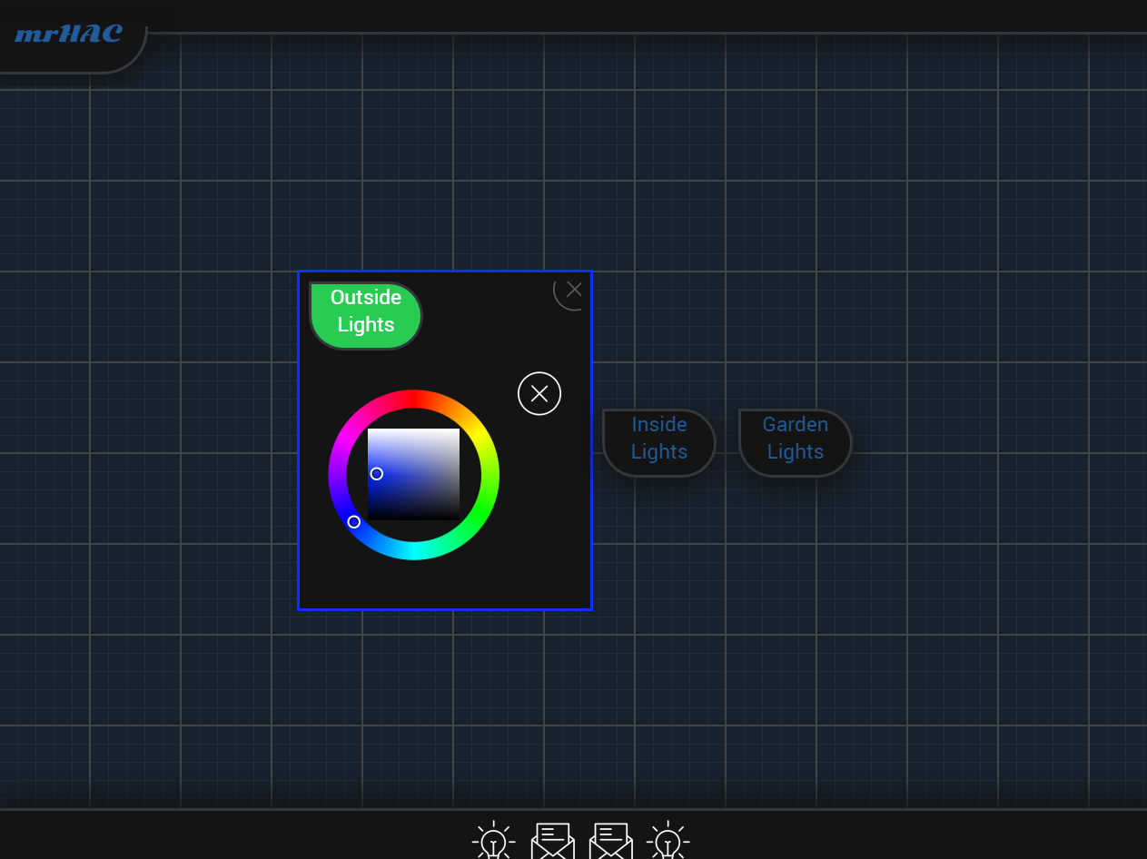
I thought I should start by at least posting something, so here are a few screen shots of the V1 web interface, V2 coming very soon :D


This future style Home Automation System is here to help simplify life without the hassle.
Already have an account? Log in.
To make the experience fit your profile, pick a username and tell us what interests you.
I thought I should start by at least posting something, so here are a few screen shots of the V1 web interface, V2 coming very soon :D
Hello there!
I bring to you some great news, I finished my ATS(Automatic transfer switch) last night! Well the 3rd prototype anyway haha.
So, I shall share some photos for you :) ... and maybe a video.
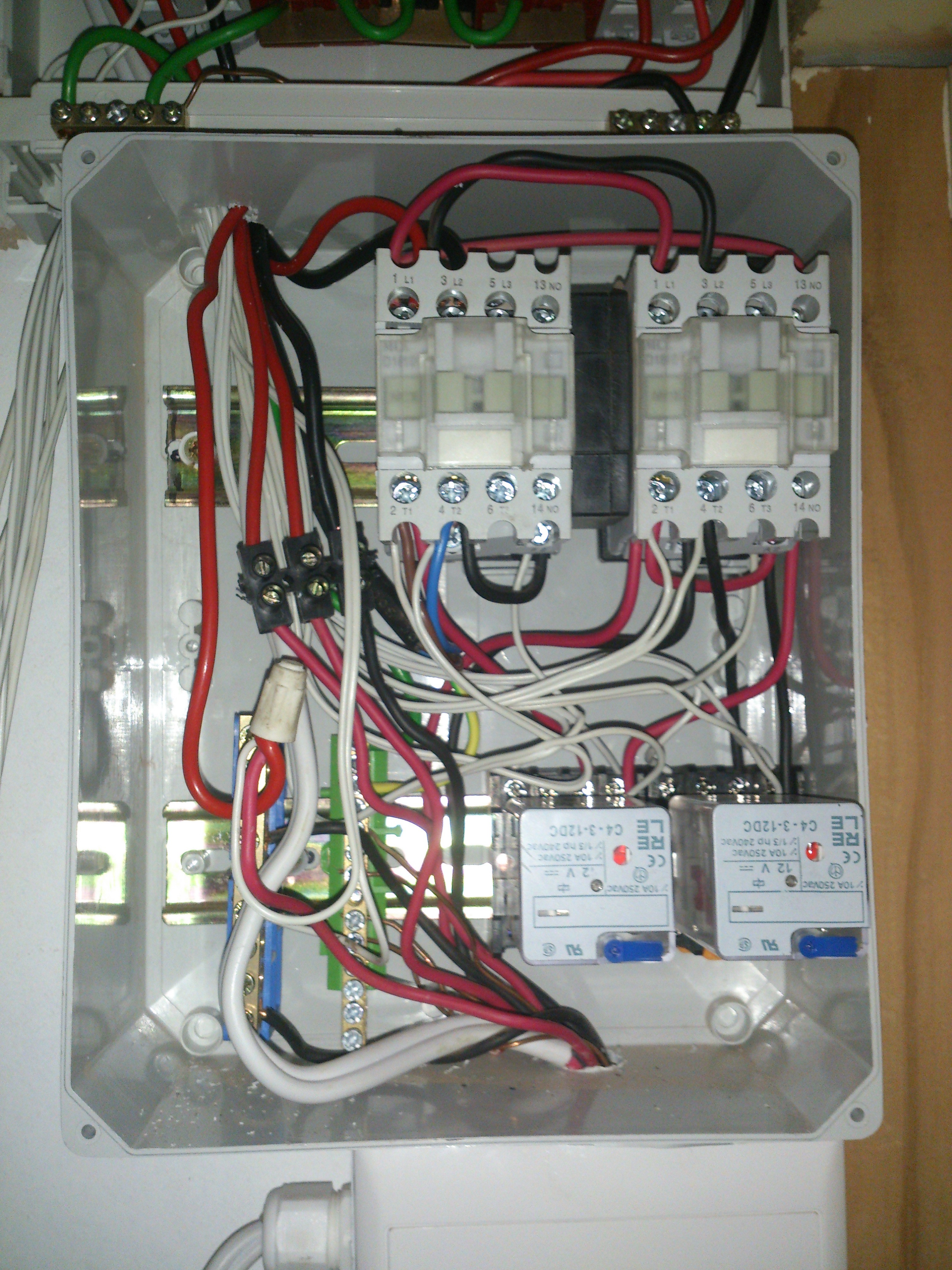
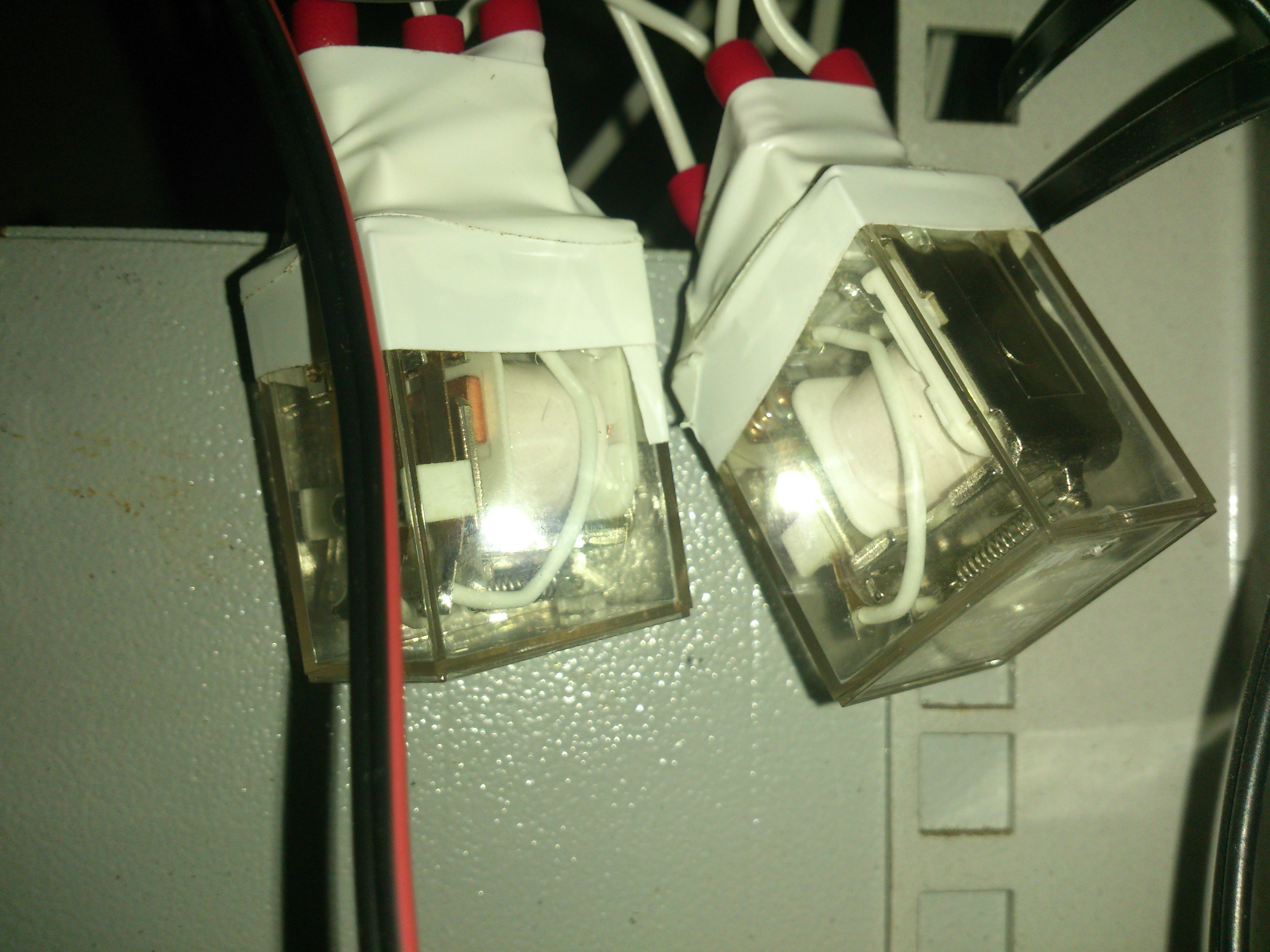
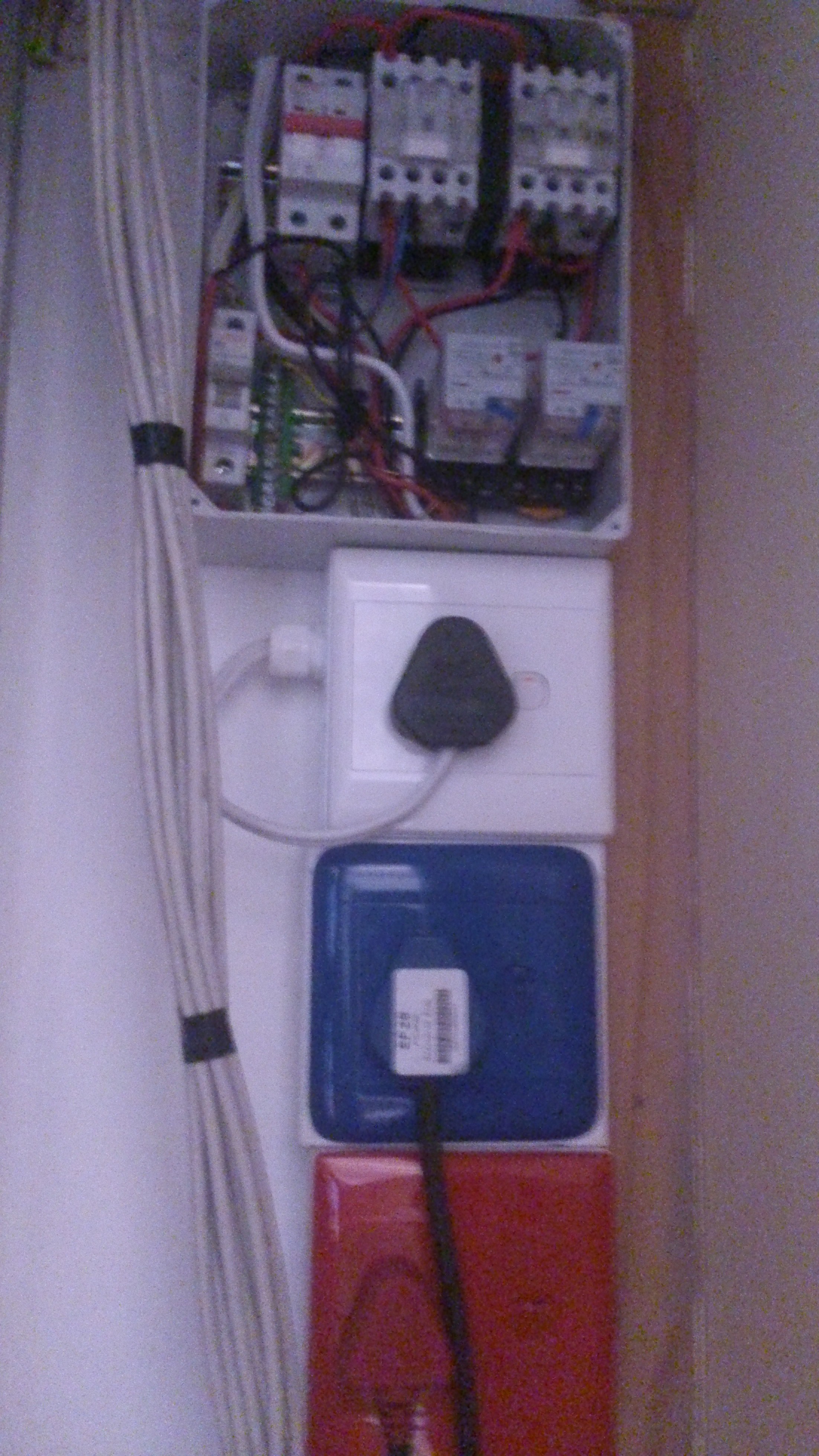
This is the actual switch unit.
The right contactor (top right) is for mains.
The left one is for generator.
(The bottom 2 are the 12v relays)
How the relay and contactors are wired:
LIVE - RELAY SWITCH - CONTACTOR IN
NEUTRAL - CONTACTOR IN
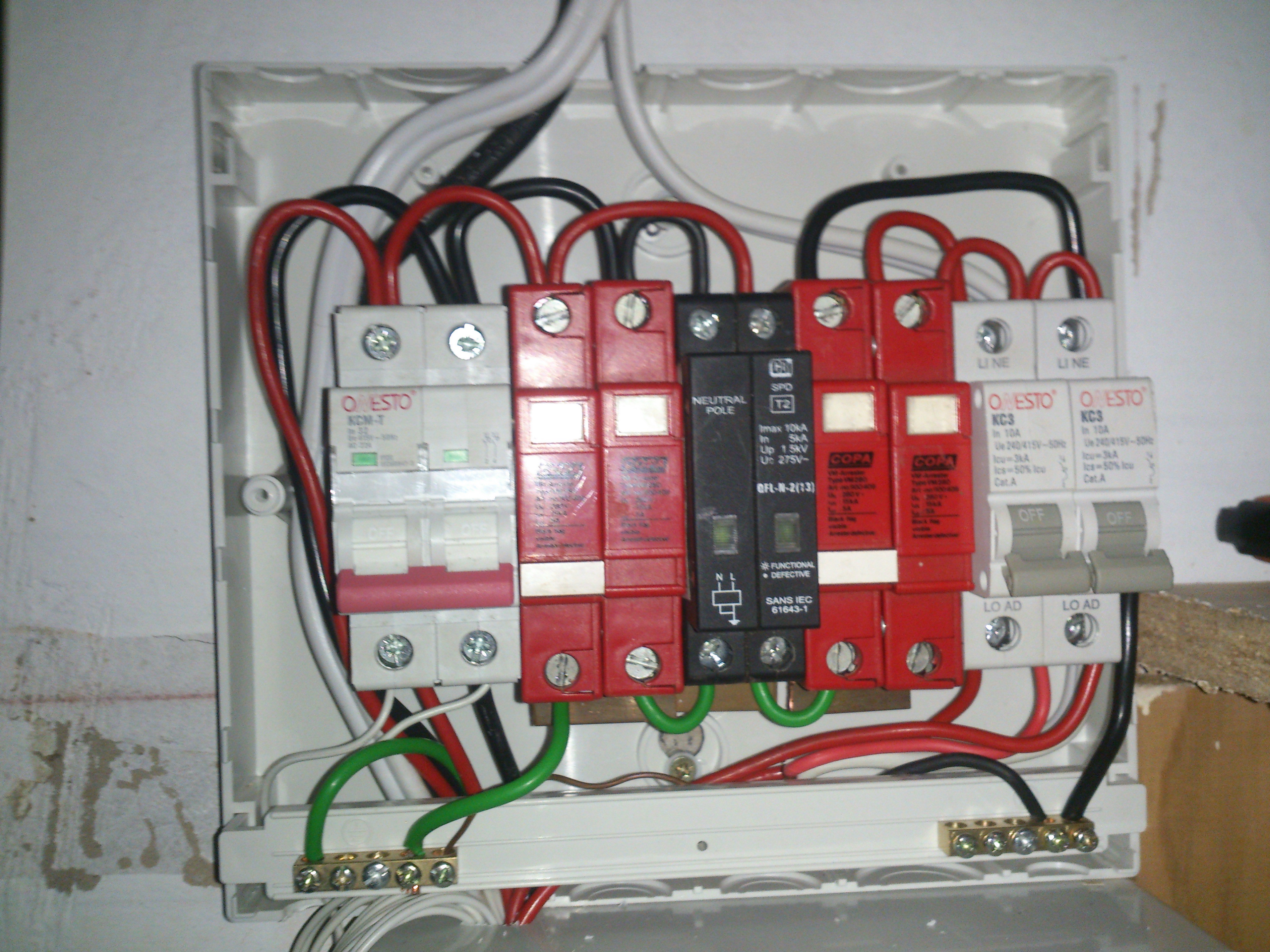
The DB board above the box:
Power from contactors go into the left isolator.
Next to it are 2 surge protectors (L+N)
In the middle (the black thing) is a wire polarity checker, if both lights aren't on, there is an issue with the power coming into the UPS.
Next is another set of surge protectors and the 2 output trip switches.
Left one for the servers and the right for the blue plugs in the house.
So Purdy <3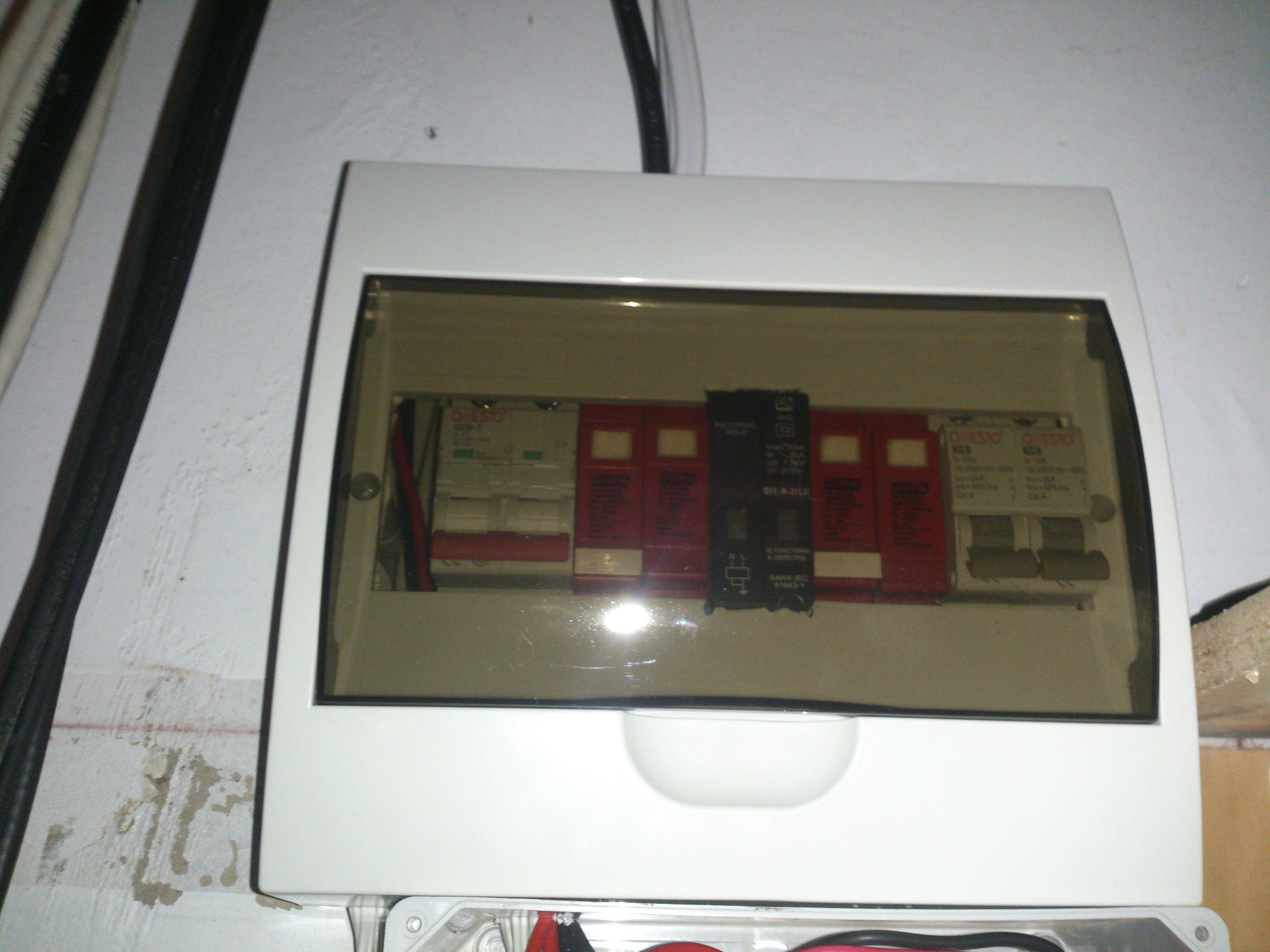
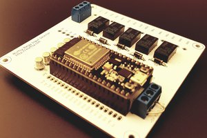
The wires in the front with the blue connectors are outputs for the 2x (12v) relays you saw above.
The wires in the back with the green connectors (not the USB cable) are opto-isolated inputs from the power inputs.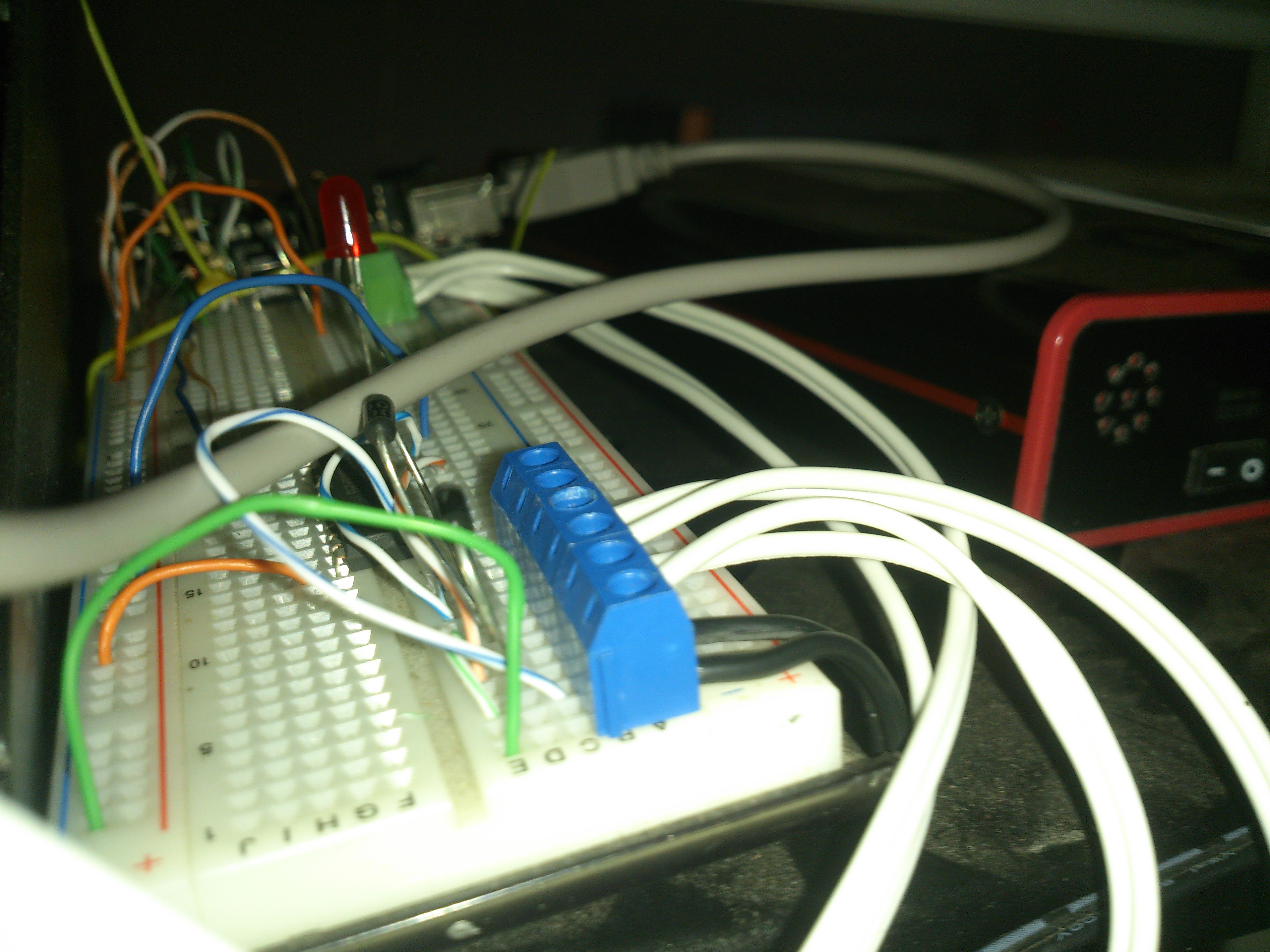
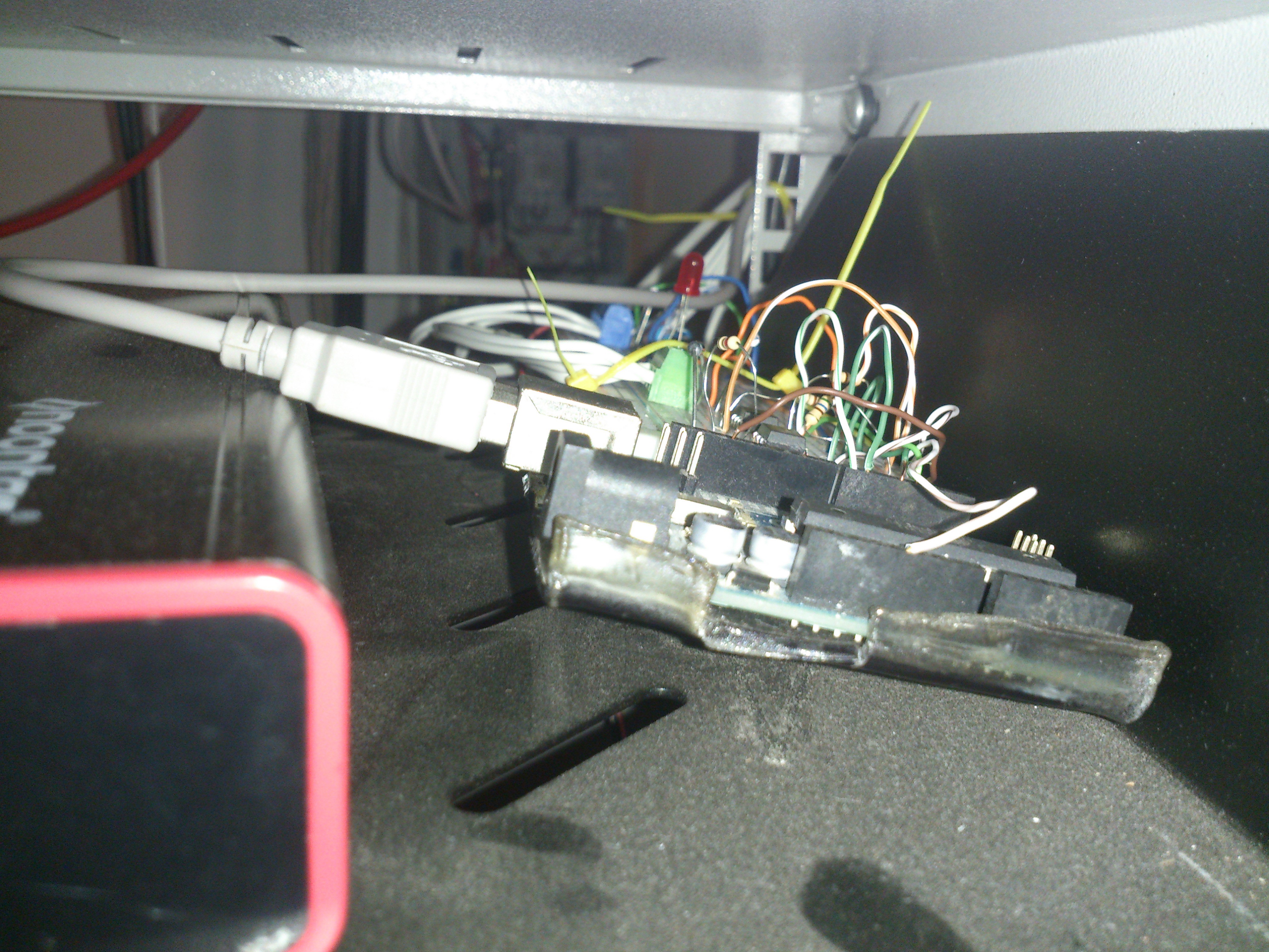
(This is how I can tell if there is power coming into the contactors)
:) So that's about it for the hardware side.
I do intend to commit all the code to GitHub but for now, a quick snippet of this code: (Please excuse the lack of comments. It was a quickie)
//Filename: mrHAC-CustomGeneratorController.ino
// This work is licensed under the Creative Commons Attribution-NonCommercial-ShareAlike 4.0 International License. To view a copy of this license, visit http://creativecommons.org/licenses/by-nc-sa/4.0/ or send a letter to Creative Commons, PO Box 1866, Mountain View, CA 94042, USA.
// Copyright Mitchell Robert (M.R. Inc) 2005 - 2015. All Rights Reserved.
// Author: Mitchell Robert (M.R. Inc)
// Date: 27/09/2015

#include "mrHAC-CustomGeneratorControllerPowerState.h";

bool EskomPower = false;
bool GeneratorPower = false;
CURRENTSWITCHSTATE CurrentSwitch = NONE;
char* GeneratorKey = "$MYGENERATOR=";
int EskomRelayPin = 3;
int GeneratorRelayPin = 4;
int EskomPowerPin = 6;
int GeneratorPowerPin = 7;

/*
 * WHEN THE INPUT IS OPEN, READ=HIGH
 *                 CLOSED, READ=LOW
 */

void setup() {
  pinMode (EskomRelayPin, OUTPUT);
  pinMode (GeneratorRelayPin, OUTPUT);
  pinMode (EskomPowerPin, INPUT);
  pinMode (GeneratorPowerPin, INPUT);

  Serial.begin(9600);

  // Force the system to recheck in case the power is currently off.
  EskomPower = !digitalRead(EskomPowerPin);
}

void loop() {
  if (digitalRead(EskomPowerPin) != (EskomPower)) {
    Serial.print("$UNKNOWN+MSG=ESKOM CHANGE TO: ");
    Serial.print(!EskomPower);
    Serial.println("$");
    delay(3000);
    if (digitalRead(EskomPowerPin) != (EskomPower)) {
      EskomPower = digitalRead(EskomPowerPin);
      Serial.print("$UNKNOWN+MSG=ESKOM CHANGED TO: ");
      Serial.print(EskomPower);
      Serial.println("$");
    }
    else
      Serial.println("$UNKNOWN+MSG=SURGE$");
  }

  if (digitalRead(GeneratorPowerPin) != (GeneratorPower)) {
    Serial.print("$UNKNOWN+MSG=GENERATOR CHANGE TO: ");
    Serial.print(!GeneratorPower);
    Serial.println("$");
    delay(3000);
    if (digitalRead(GeneratorPowerPin) != (GeneratorPower)) {
      GeneratorPower = digitalRead(GeneratorPowerPin);
      Serial.print("$UNKNOWN+MSG=GENERATOR CHANGED TO: ");
      Serial.print(GeneratorPower);
      Serial.println("$");
    }
    else
      Serial.println("$UNKNOWN+MSG=SURGE$");
  }

  if (!EskomPower && CurrentSwitch == ESKOM) {
    SwitchStateTo(GENERATOR);
  }
  else if (EskomPower && CurrentSwitch == GENERATOR) {
    SwitchStateTo(ESKOM);
  }

  else if (!EskomPower && CurrentSwitch == NONE) {
    SerialPrintData("0");
    delay(10000);
    SwitchStateTo(GENERATOR);
  }
  else if (EskomPower && CurrentSwitch == NONE) {
    delay(10000);
    SwitchStateTo(ESKOM);
  }
}

void SwitchStateTo(CURRENTSWITCHSTATE state) {
  Serial.print("$UNKNOWN+MSG=SWITCHING TO ");
  Serial.print(CURRENTSWITCHSTATE_STRING[state]);
  Serial.println("$");
...
Read more »
Hello again,
so I think it is about time I post another update haha.
**********************************
Do not try this at home unless you know what you are doing and have experience in this field - 120/240v CAN KILL!
**********************************
... Now that is out of the way, lets get messy :D
So due to our South African Load Shedding problem, I have made my own ATS (currently MTS) switch over system for my house.
* By using a white plug instead of connecting directly with the main DB board: it stops me from having to pay an electrician to COC the work as well as getting a 9000 ZAR (That's a lot - a 2.5Kva petrol generator (with AVR and electric start) is 5000 ZAR) SABS approved switch over panel and generator installation certificate.
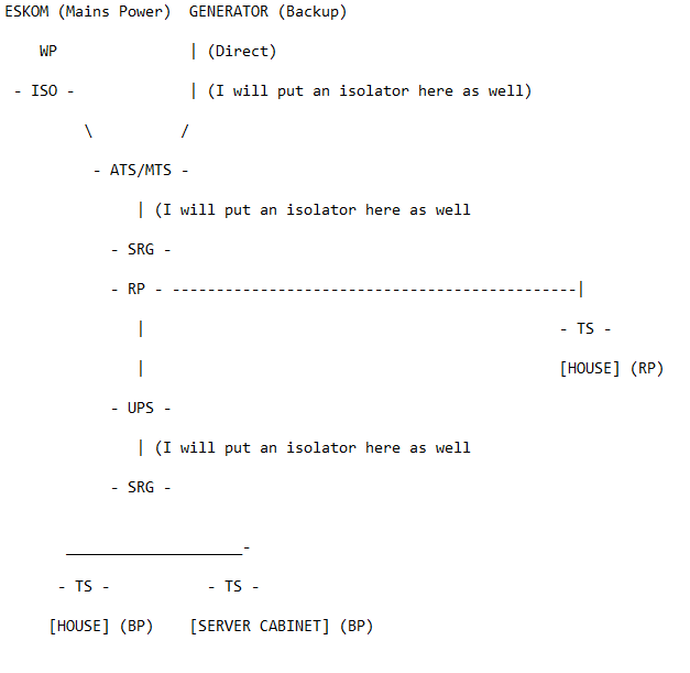
Keys:
* TS = Trip Switch - (10-20AMP)
* RP = Red Plug
* BP = Blue Plug
* WP = White Plug
* ISO = Isolator (2 pole - 20AMP)
* UPS = Online 3Kva Rack Mount UPS
* SRG = Surge protector, any type should do, I am using a VM280 3 phase set.
* I bought all my parts from MCE (www.mce.co.za)
So here is my wiring design:
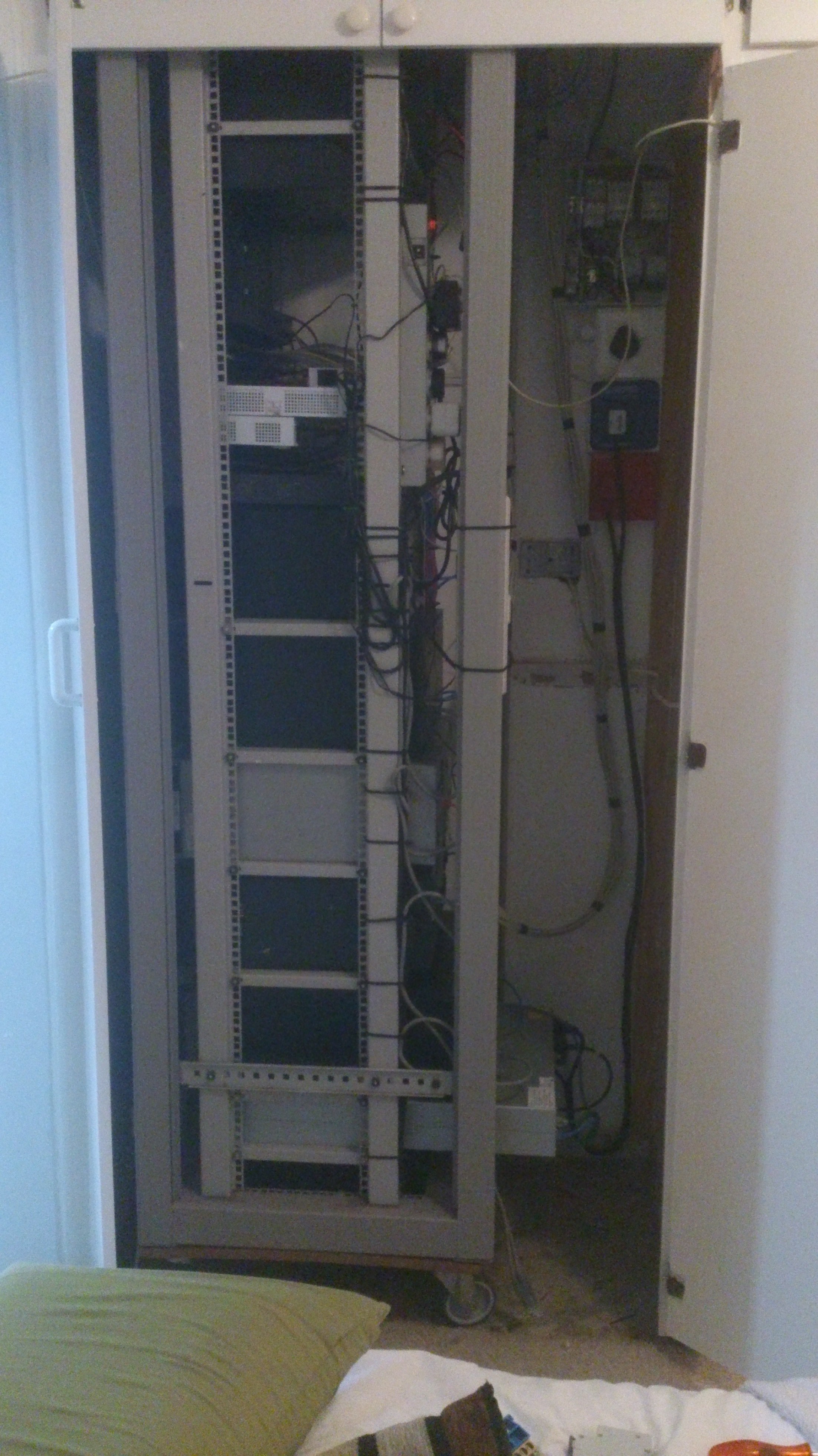
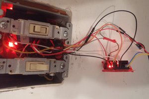
And of course, some pics:
(No comment on the mess of the wiring please :D - I was waiting for a part but needed the system to work for now, will upload some more pics when it is completed. - Hopefully by the end of tomorrow)
Just another update, I have been working on the new GUI design.


 thjubeck
 engineerkid1
 Eduardo Zola