 Ossum
Ossum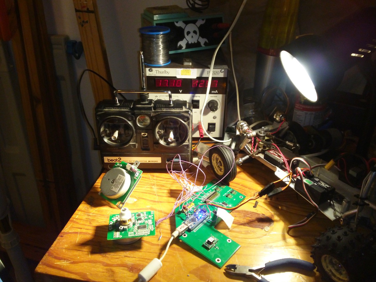
Real life got in the way for my friend doing the CNC-cutting, so there are still no parts. In the meantime I decided to get stuck into the motor control.
I pulled these motors from an HP Color LaserJet 3000 series printer a few months back. After some digging I discovered that googling "HP Printer <number> service manual" invariably brings up some pretty decent documentation.
Since I really wasn't sure whether the motor would even have enough power for my purposes, I whipped up a quick prototype with an Arduino Nano clone to test it out. If I end up using the motor I will build a little board and port the code to an ATTINY85 or similar.
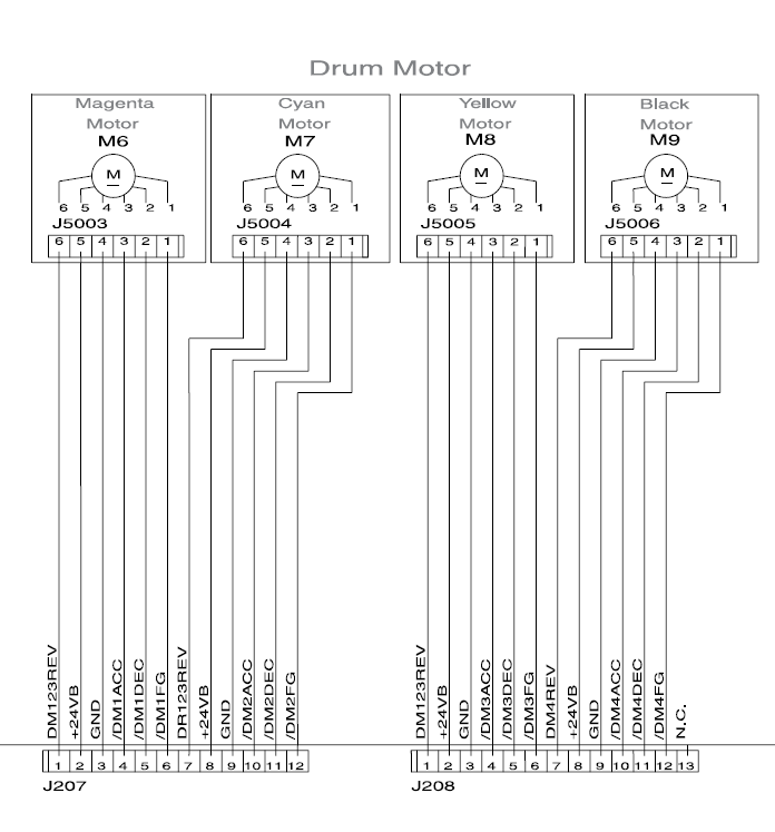
The control signals are pretty simple (I am using 5V logic, which it seems happy with)
- /ACC requires a PWM for speed control
- /DEC is a "brake" (I think of it as an enable pin)
- REV controls direction
- FG is an output which can be used for closed-loop control
The biggest nuisance is that the motors require 24V DC, not a great voltage for standard RC batteries.
I have it running off a bench supply at 24V at the moment, the Arduino is sitting on an old board left over from another project, which works out well, since it has a 5V switch-mode supply on it, to feed the Nano and the RC receiver.
The Nano listens for standard RC servo signals from the receiver (this post was handy) and sets the pins for the motor accordingly. I had to increase the PWM frequency of the Arduino and found this TimerOne library made it easy-peasy.
I have some video of the motor running, but my internet is being ridiculously slow, I will upload it when possible, so that you can all bask in its glorious whine. I can't say for sure yet whether the motor will work for the boat. It spins with enough torque that the 6mm shaft burns my fingers when I try to stop it, but my finger-heat to thrust calculations are a bit rusty. Once I figure out how to mount a prop I will know more (or just lose my fingers all together).
UPDATE: here is the video, as filmed with a shaky low-resolution potato
The code is attached below, in case anyone is interested
// Jason Suter 24/07/2015
// Built for https://hackaday.io/project/6660-airscrew-driven-rc-boat
// Code designed to control a brushless DC motor from an HP printer (RK-0934 or similar)
// RC signal interpretation from this blog post http://rcarduino.blogspot.com/2012/01/how-to-read-rc-receiver-with.html


#include <TimerOne.h>


#define THROTTLE_SIGNAL_IN 0 // INTERRUPT 0 = DIGITAL PIN 2 (I think)- use the interrupt number in attachInterrupt
#define THROTTLE_SIGNAL_IN_PIN 2 // INTERRUPT 0 = DIGITAL PIN 2 - use the PIN number in digitalRead
#define NEUTRAL_THROTTLE 1500 // this is the duration in microseconds of neutral throttle on an electric RC Car
#define DEADZONE 50 // microseconds of deadzone
#define KILLTIME 50 // if there is no pulse received after this duration (milliseconds), then kill the motor


int stopPin = 3;
int pwmPin = 9;
int revPin = 7;

volatile int inputPulseLength = NEUTRAL_THROTTLE; // volatile, we set this in the Interrupt and read it in loop so it must be declared volatile
volatile unsigned long ulStartPeriod = 0; // set in the interrupt
volatile unsigned long killStartPeriod = 0; // set in the interrupt
volatile unsigned long invertedPulseLength = 0; // micros of new pulse we need to put out (3000 - lastPulse)
volatile boolean bNewPulse = false; // set in the interrupt and read in the loop


// the setup function runs once when you press reset or power the board
void setup() {
  //timer setup
  Timer1.initialize(300);
  Timer1.pwm(9, 512);

  // initialize digital pin 13 as an output.
  pinMode(stopPin, OUTPUT);
  pinMode(pwmPin, OUTPUT);
  pinMode(revPin, OUTPUT);

  pinMode(13, OUTPUT);

  digitalWrite(stopPin, true);

  attachInterrupt(THROTTLE_SIGNAL_IN,calcInput,CHANGE);

  Serial.begin(9600);

}


// the loop function runs over and over again forever
void loop() {


    if (bNewPulse) {
      int pulseDelta = min(max(abs(inputPulseLength - NEUTRAL_THROTTLE),0),400);
      int newPwm = map(pulseDelta,DEADZONE,400,0,1023);
      Timer1.pwm(pwmPin, newPwm);

      if ((inputPulseLength > NEUTRAL_THROTTLE) && (pulseDelta > DEADZONE)) {
        //Serial.print("forwards");
        //Serial.println(pulseDelta);
        //Serial.print("newpwm");
        //Serial.println(newPwm);
        digitalWrite(revPin, false);
        digitalWrite(stopPin, false);
      }
      else if ((inputPulseLength < NEUTRAL_THROTTLE) && (pulseDelta > DEADZONE)) {
        //Serial.print("backwards");
        //Serial.println(pulseDelta);
        //Serial.print("newpwm");
        //Serial.println(newPwm);
        digitalWrite(revPin, false);
        digitalWrite(stopPin, false);
      }
      else {
        //Serial.println("stop");
        digitalWrite(stopPin, true);
        Timer1.pwm(pwmPin, 0);


      }
      bNewPulse = false;

    }

    if ((millis() - killStartPeriod) >  KILLTIME) {
      digitalWrite(stopPin, true);
      Timer1.pwm(pwmPin, 0);
      //Serial.println("stopped - signal lost");
    }


}


void calcInput()
{
  // if the pin is high, its the start of an interrupt
  if(digitalRead(THROTTLE_SIGNAL_IN_PIN) == HIGH)
  {
    // get the time using micros
    ulStartPeriod = micros();
    killStartPeriod = millis();
  }
  else
  {

    // if the pin is low, its the falling edge of the pulse so now we can calculate the pulse duration by subtracting the
    // start time ulStartPeriod from the current time returned by micros()
    inputPulseLength = (int)(micros() - ulStartPeriod);
    ulStartPeriod = 0;

    // tell loop we are outputting a new pulse
    bNewPulse = true;
    //Serial.print("new pulse ");
    //Serial.println(inputPulseLength);

  }
}
Discussions
Become a Hackaday.io Member
Create an account to leave a comment. Already have an account? Log In.