 Göran Nordahl
-
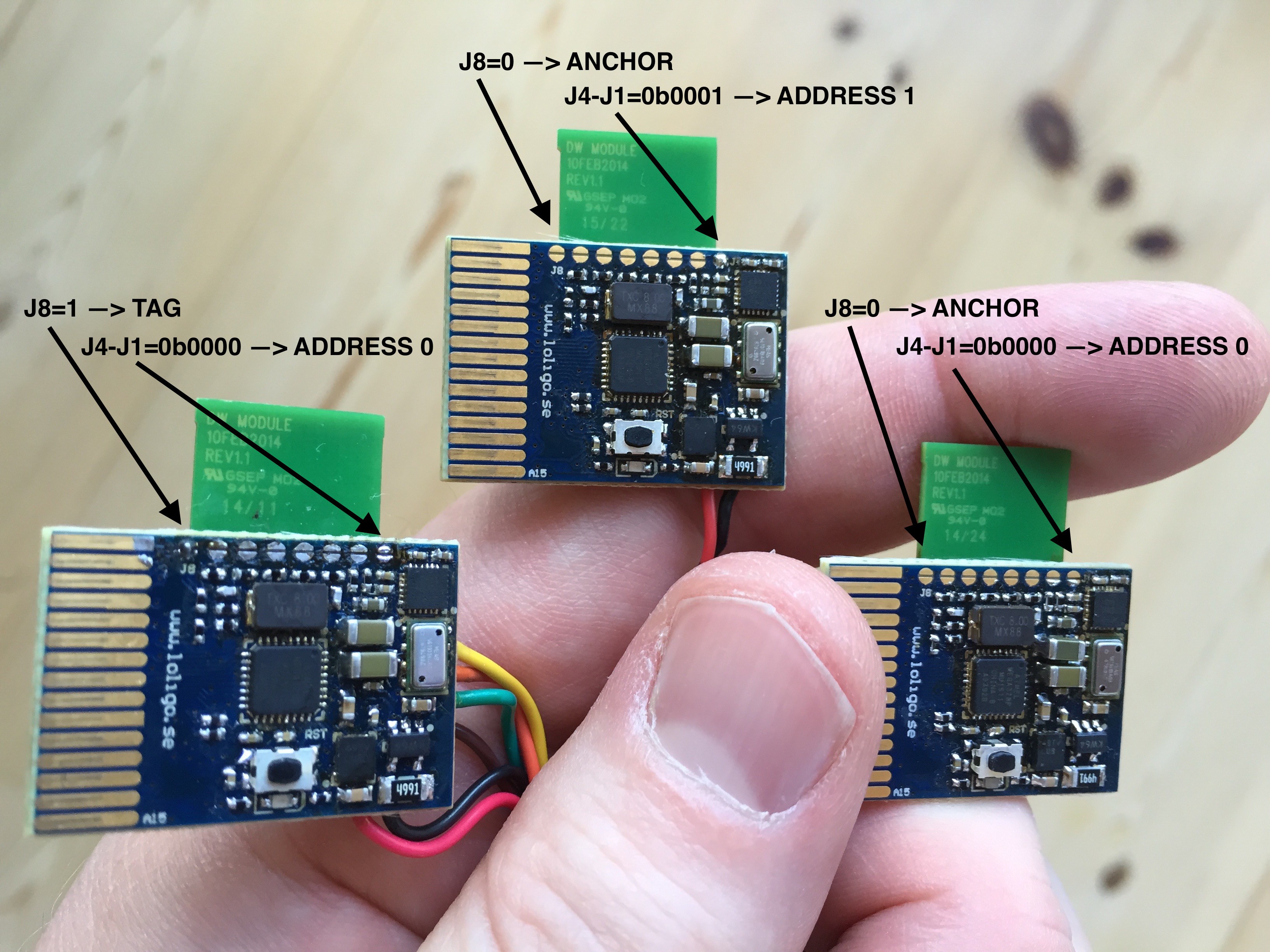
1Step 1
Configure the boards to be tag/anchor and give them individual addresses. J8 decides tag(1)/anchor(0) and J4-J1 sets the address. A tag and anchor can have the same address since tags and anchors are handled separatley. J7-J5 is not used by our demo software, but can of course be used either for configuration or more address space. If you are not fond of soldering it is just to store the configuration in EEPROM instead. Just a matter of code.
![]()
-
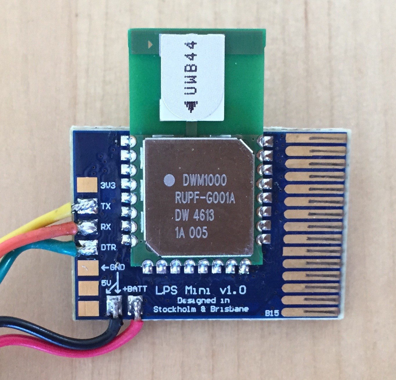
2Step 2
Normally a tag reports measurements via UART. By adapting the firmware also I2C/SPI can be used, but that will decrease the update rate due to bus bandwidth limitations. In this example we are using the UART connected to a USB to TTL converter. 3.5-5V is supplied by connecting a LiPo battery or power supply directly between +BATT and GND. The 5V pad is used to charge the LiPo and is of no use if using an external power source.
The serial interface and power connections are also available via the board edge connector.![]()
-
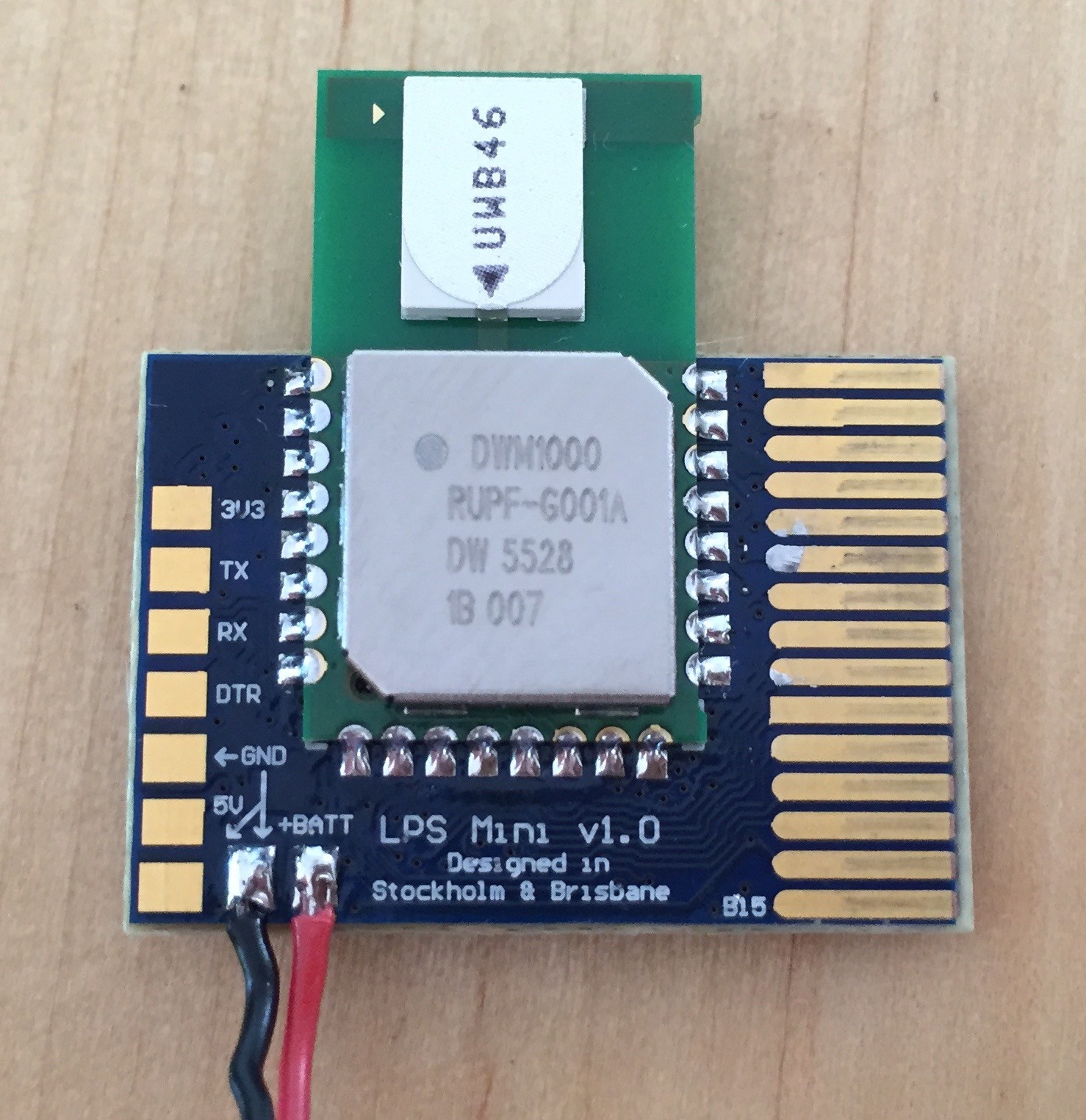
3Step 3
An anchor do not need to report anything to an external MCU, so it only requires power.
![]()
-
4Step 4
Plug in the USB to TTL converter to a computer. Setup a terminal program for 115200-8-N-1 (earlier versions used 57600-8-N-1) and you will see something like this:
LPSMini v1.0 Setup
DIP L:1021, 0 H:510, 8:0x80
DECA0130
Tag addr: DECA01000
Setup done
.As soon as the first anchor is powered up the terminal program will fill up with distance measurements (in this case me walking with a tag in my hand from 14.405m towards the anchor):
DECA02000 LAST: 14405mm P: -100.4
DECA02000 LAST: 13951mm P: -101.7
DECA02000 LAST: 13421mm P: -99.1
DECA02000 LAST: 12962mm P: -92.7
DECA02000 LAST: 12170mm P: -97.6
DECA02000 LAST: 10977mm P: -96.6
DECA02000 LAST: 10613mm P: -98.4
DECA02000 LAST: 9928mm P: -94.1
DECA02000 LAST: 9224mm P: -93.4
DECA02000 LAST: 8657mm P: -100.2
DECA02000 LAST: 8104mm P: -97.8
DECA02000 LAST: 7810mm P: -94.5
DECA02000 LAST: 7863mm P: -93.5
DECA02000 LAST: 7035mm P: -92.3
DECA02000 LAST: 6459mm P: -95.0
DECA02000 LAST: 6191mm P: -94.6
DECA02000 LAST: 5847mm P: -93.9
DECA02000 LAST: 5837mm P: -87.9
DECA02000 LAST: 5898mm P: -92.3
DECA02000 LAST: 6465mm P: -96.9
DECA02000 LAST: 6309mm P: -88.4
DECA02000 LAST: 5276mm P: -86.5
DECA02000 LAST: 5049mm P: -84.5
DECA02000 LAST: 4160mm P: -85.9
DECA02000 LAST: 3691mm P: -81.5
DECA02000 LAST: 2991mm P: -80.2
DECA02000 LAST: 2442mm P: -80.8
DECA02000 LAST: 1912mm P: -80.3
DECA02000 LAST: 1524mm P: -80.3
DECA02000 LAST: 1184mm P: -80.6
DECA02000 LAST: 868mm P: -81.2
DECA02000 LAST: 505mm P: -80.2
DECA02000 LAST: 293mm P: -80.3
DECA02000 LAST: 165mm P: -80.4
DECA02000 LAST: 151mm P: -80.7
DECA02000 LAST: 127mm P: -80.1
DECA02000 LAST: 83mm P: -80.2Both distance in mm and signal strength in dBm are reported, hence the "P:" at the end.
With three anchors (address 0, 1 and 2) the output will look like this:
DECA02000 LAST: 10065mm P: -100.3
DECA02001 LAST: 5971mm P: -85.3
DECA02002 LAST: 5485mm P: -85.4
DECA02000 LAST: 10053mm P: -98.3
DECA02001 LAST: 5945mm P: -84.3
DECA02002 LAST: 5500mm P: -85.4 -
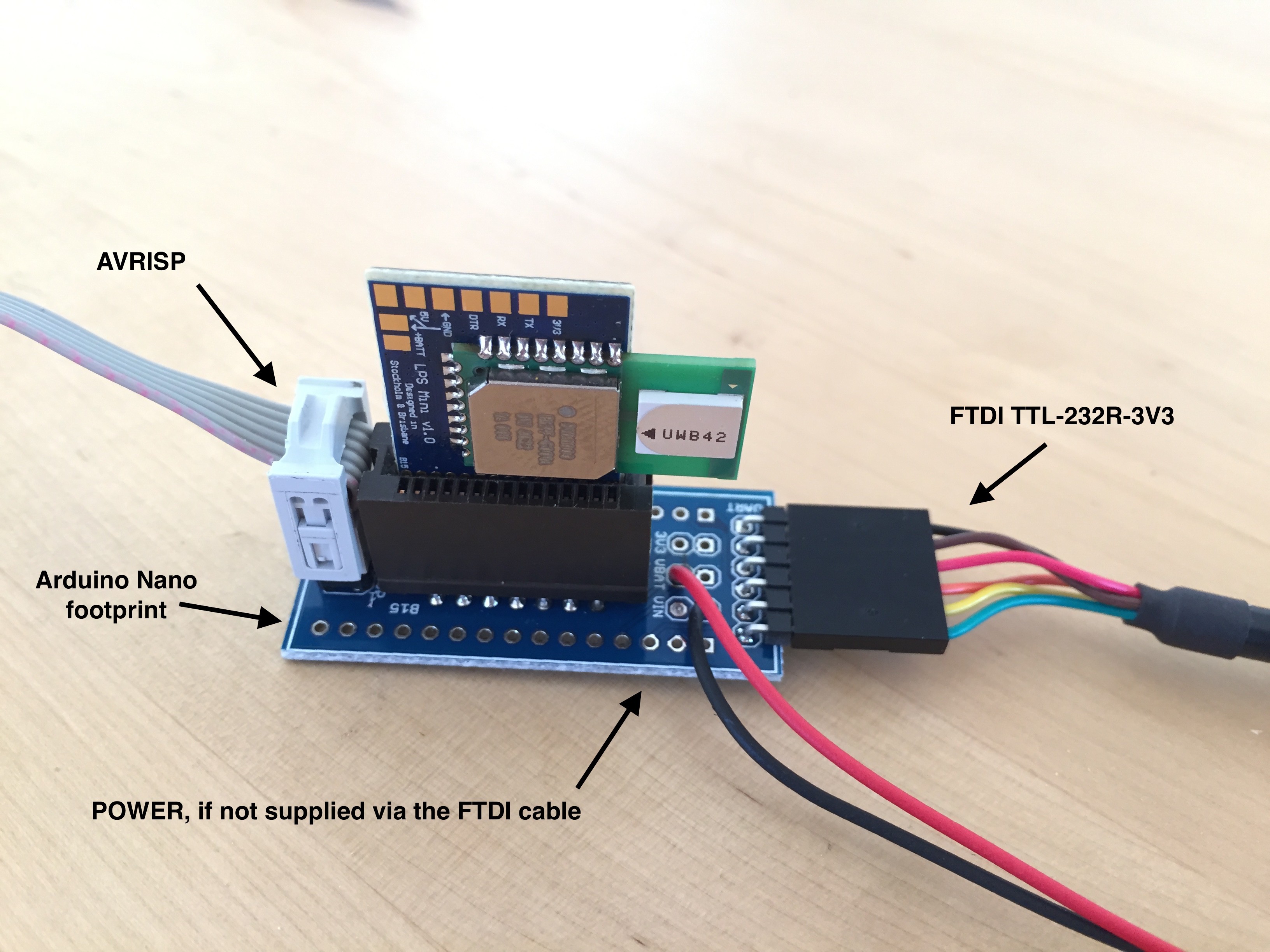
5Step 5
If you ever need to upgrade the supplied bootloader or change a fuse in ATmega328P, the LPS Mini Adaptor will come in handy. It is also very practical during test and debug and makes it easy to access all power pins and I/O.
![]()
LPS Mini
Arduino compatible indoor navigation system with small form factor.
Discussions
Become a Hackaday.io Member
Create an account to leave a comment. Already have an account? Log In.
We have reached a maximum of 328m outdoors: From 59°19'11.27”N, 18° 3'42.14”E (just outside my lab) to 59°19'9.00”N, 18° 3'21.91”E (ugly house). We could not get further due to the ugly house blocking our way. We had enough antenna height and free space along the way so the first Freznel zone was without any obstructions: https://en.m.wikipedia.org/wiki/Fresnel_zone. We used maximum output power, longest possible preamle and channel 5. It is also very important with proper decoupling, a good PCB layout and a stable power supply. For normal use there is most often obstacles in the way thus reducing the range. 100-200m is a more reasonable distance outdoors, depending on your environment. Indoor use is very dependant on the material in your walls and other objects acting as attenuators/reflectors. 30-50m should be no problem in an open environment. Inside a warehouse there will be areas with more or less completely blocked RF signal path, but that can be handled with more anchors in the ceiling.
Are you sure? yes | no
Hi. You could achieve the maximum range described by Decawave? Indoor 30-50meters and outdoor 200-300meters. Do you have conducted some test?
Are you sure? yes | no