 leadacid44
Well, now that I had a plan of attack, it was time to take things apart. I took to the keyboard and did a little cleaning while I was in there, and was somewhat surprised (even with the fore-knowledge of how it was supposed to work) at the construction.
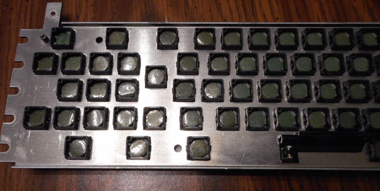
The Compaq Portable (and a few other Compaq systems from that era) uses an interesting arrangement for it's keyboard. The keyboard switches aren't switches in the traditional sense, like the mechanical, buckling spring, or even rubber-dome contacts like many of the other popular types available at the time or since. Instead, the keyboard behaves somewhat like the modern capacitive touchscreen, albeit on a much larger, much less transparent, scale.
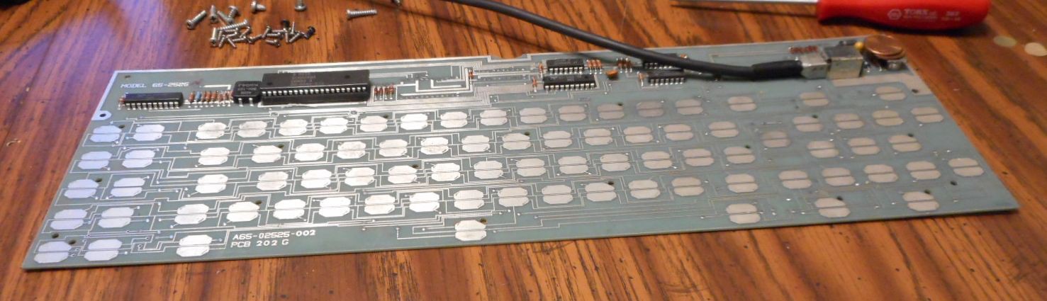
The keyboard has three components: the physical plastic keycap and traveling spring, the plastic-foam-mylar contact disk, and the keyboard PCB itself. As Philip describes in his article, and as the others at the Vintage Computer Forums mention, the keyboard doesn't necessarily sense an electrical contact, but senses the capacitance of that contact disk, which than triggers the input. Interestingly, human fingertips can also be used in lieu of the plastic keyboard parts.
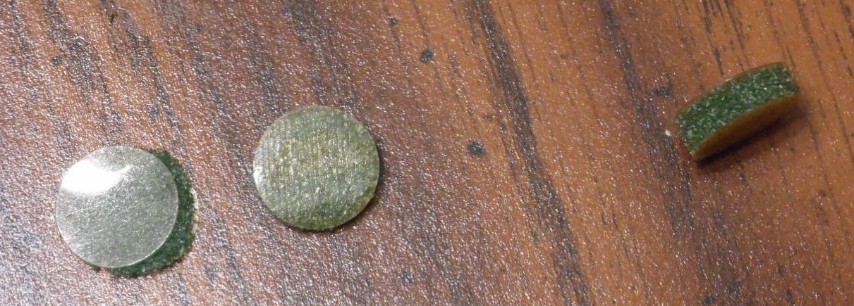
Here you can see three old disks. The left most one is plastic side up, the middle one mylar side up, and the rightmost is on edge. These are the three best ones I could remove! As you can see on the left, the foam is already disintegrating.
The idea is that this disk is connected to the bottom of the keycap, which is then held slightly above the PCB until it is depressed and contacts the surface. When it does, the mylar changes the capacitance value for that key, triggering the input.
The foam allows a little give between the trigger of the input and the bottoming of the keystroke, in theory yielding a lighter touch than a purely mechanical switch would.
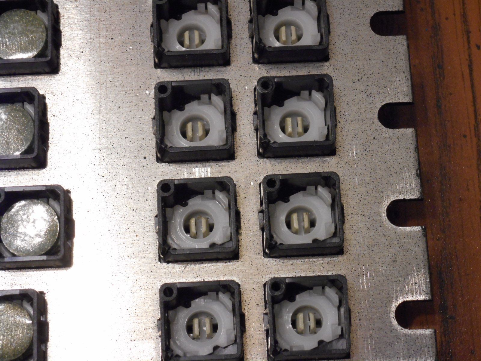
Here is a closeup of the keycaps themselves. You can see the little white plastic clips that the disc snaps into, four per key. This will come up later.
So overall, its a rather interesting approach, and I'm not sure why this was chosen over a more traditional setup. Cost I suppose. Perhaps weight as well?
Well, either way, the crux of our problem is that plastc-foam-mylar sandwich I keep talking about. Well, what seems to happen is that over time, that foam will slowly degrade and either turn to dust or turn to a sticky goo. Mine had gone down the dust road. Perhaps more interesting was that when I picked up a piece of the mylar disc and tried to use it on the keyboard manually, it also did not trigger! So how to create a new set of disks?
Discussions
Become a Hackaday.io Member
Create an account to leave a comment. Already have an account? Log In.